সমান্তরাল শ্যাফট বনাম রাইট-অ্যাঙ্গেল গিয়ার মোটর: কোনটি আপনার মেশিনের জন্য উপযুক্ত?
রাইট-অ্যাঙ্গেল বনাম ইনলাইন গিয়ার মোটর: বাস্তব অনুমোদিত লোড টেবিলের তুলনায় দক্ষতা, টর্ক, স্ব-লকিংয়ের মিথ এবং পাঁচ ধাপে কীভাবে সিদ্ধান্ত নেবেন।.
আরও পড়ুন
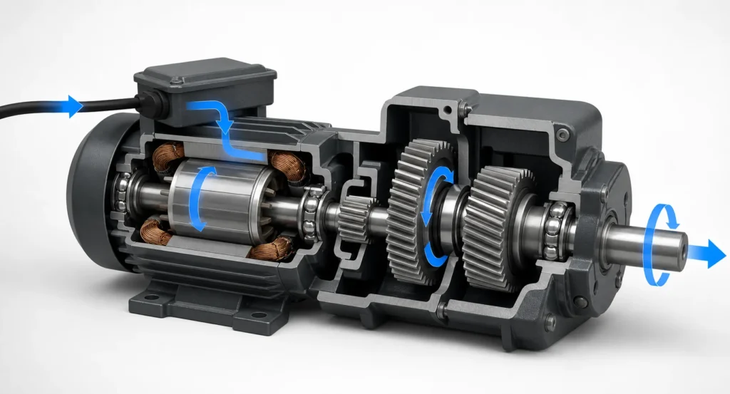
A গিয়ার রিডাক্সার মোটর works by combining an electric motor with a reduction gearbox. Electrical energy creates high-speed rotation in the motor. A small input gear then drives one or more larger gears, lowering output speed while increasing usable torque. The final output shaft transfers that slower, stronger rotation to a conveyor, feeder, mixer, turntable, or other machine.
The reducer does not create extra power. Instead, it trades speed for torque while losing a small amount of energy to gear friction, bearings, seals, and lubricant movement. Understanding that power path makes it easier to select the right ratio, motor size, voltage, and mounting arrangement. টেনচুয়ান হোম page provides an overview of its compact industrial drive products.
Although gearmotor designs vary, most integrated units contain the same functional groups:
An integrated design keeps the motor pinion and gearbox input accurately aligned. This eliminates a separate coupling between the motor and reducer, reduces installation space, and can simplify machine assembly.
In a small AC induction gearmotor, alternating current flows through the stator windings and creates a rotating magnetic field. That field induces current in the rotor, producing electromagnetic torque. The rotor follows the rotating field and turns the motor shaft.
The rotor usually runs slightly below the field’s synchronous speed because induction requires slip. Supply frequency, motor pole count, design, and load determine the actual rated speed. This is why a 50Hz and 60Hz version may produce different motor and geared output speeds even when the physical unit looks similar.
A DC gearmotor works differently on the electrical side. A brushed DC motor uses a commutator and brushes, while a brushless motor uses electronic commutation. However, after the motor shaft begins turning, the mechanical reduction principle is essentially the same: the gear train exchanges speed for torque.
দ্য gear reduction gearbox contains one or more gear pairs. A small driver gear on the input shaft meshes with a larger driven gear. Because the larger gear has more teeth, the input gear must rotate several times to turn it once.
The basic relationship is:
Reduction ratio = input speed / output speed
If the motor runs at 1,500 rpm and the required output is 50 rpm, the nominal ratio is:
1,500 / 50 = 30:1
The input shaft turns about 30 times for one output revolution. In an ideal loss-free reducer, torque would rise by the same factor. Real gearboxes have losses, so a useful estimate is:
Output torque = motor torque × ratio × gearbox efficiency
For example, a motor delivering 0.4 N·m through a 30:1 reducer at 85% efficiency would produce an estimated 10.2 N·m:
0.4 × 30 × 0.85 = 10.2 N·m
This is only a preliminary calculation. The selected gearhead’s rated allowable torque, shaft capacity, thermal limit, duty cycle, and service factor must also be checked.
Startup is often the most demanding period. Conveyor mass, friction, acceleration, and load inertia can require more torque than steady running. Frequent starts, reversals, or jams also generate additional heat and gear stress, so a motor should not be selected from continuous running torque alone.
A single gear pair can provide a moderate ratio, but very large differences in gear size may be impractical. Designers therefore divide a high total ratio across two or more stages. The stage ratios multiply together.
For example, a first stage of 5:1 and a second stage of 6:1 produce a total ratio of 30:1. Multiple stages allow a compact package, but every mesh introduces friction, heat, backlash, noise, and manufacturing tolerances. Higher ratio is therefore not automatically better; it must still deliver the required output speed efficiently.
| Gear arrangement | Output layout | Typical characteristics | Common applications |
|---|---|---|---|
| Spur or helical stages | Parallel or offset shaft | Direct, compact transmission; helical teeth can run smoothly | Conveyors, feeders, packaging |
| গ্রহীয় | ইনলাইন/কোঅ্যাক্সিয়াল | Load sharing and high torque density | Compact automation, positioning |
| কৃমি | Right angle | Large reduction in a compact 90-degree layout; efficiency varies | Gates, turntables, space-limited drives |
| বেভেল বা হাইপয়েড | Right angle | Directional change with different efficiency and load behavior | Conveyors, mixers, transfer equipment |
For compact industrial applications, review the ছোট এসি গিয়ার রিডুসার মোটর category and compare the exact gearhead, ratio, output shaft, and mounting options rather than relying on the product family name alone.
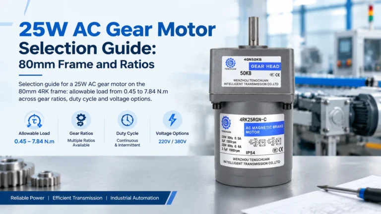
Motor wattage describes power capacity, while the ratio determines how that power is delivered as speed and torque. Product comparisons should always use both. A ২৫ ওয়াটের ছোট এসি গিয়ার রিডাক্সার মোটর may suit light feeders and indexing mechanisms. A ৬০ ওয়াট মডেল can be evaluated for small rollers and conveyors. Packaging transfers may lead to the ১২০ ওয়াট মডেল, while more demanding compact machinery can be compared with the ২০০ ওয়াট মডেল.
These examples identify available product classes, not automatic selections. Verify output rpm, allowable torque, duty cycle, service margin, shaft loads, voltage, frequency, phase, mounting, and ambient conditions for the exact configuration.
The supply decides which frame sizes are even available, so it belongs near the top of any selection, not at the end. A compact AC gear reducer motor is built for one of two supply types:
| Supply | Typical frames | Notes |
|---|---|---|
| Single-phase 110 V, 50/60 Hz | 15–300 W (small frames) | Two supply leads plus a run capacitor; direction reversed by swapping the capacitor leg. Common where only a domestic supply is available. |
| Single-phase 220 V, 50/60 Hz | 15–300 W (small frames) | Same wiring logic on a 220 V supply. Most common in Southeast Asian light industry. |
| Three-phase 220 V | 25–300 W and 400–3700 W | No capacitor, three leads. Direction reversed by swapping any two phases. Smoother starting torque. |
| Three-phase 380 V | 400–3700 W (medium frames) | Standard industrial supply. Always confirm phase rotation before commissioning a lifting axis. |
Two practical consequences. A single-phase motor needs its capacitor matched to the supply frequency — a 50 Hz capacitor on a 60 Hz supply loses starting torque. And a three-phase motor cannot simply be run from a single-phase supply through a static converter at full rating; if the site has no three-phase, the honest answer is to stay inside the small frames.
A gear reducer motor turns electrical energy into high-speed rotor motion, passes it through a calculated gear ratio, and delivers lower-speed, higher-torque rotation to the load. Reliable performance depends on matching every stage—from supply and winding to gears, bearings, output shaft, and driven machine.
Explore Tenchuan’s সমাধানসমূহ for application context and visit আমাদের সম্পর্কে for manufacturing background. For a project-specific recommendation, send the load, speed, torque, voltage, and installation details through আমাদের সাথে যোগাযোগ করুন.
Yes. It increases output torque approximately in proportion to the reduction ratio, reduced by gearbox losses and limited by the gearhead and shaft ratings.
Divide the motor’s loaded speed by the reduction ratio. Confirm the result against the manufacturer’s rated output speed at the actual voltage and frequency.
Heat comes from motor winding losses, gear friction, bearings, seals, frequent starts, overload, poor ventilation, and unsuitable low-speed operation. Compare measured temperature with the permitted rating.
Only when pulley tension and overhung load remain within the specified radial-load rating. Otherwise support the pulley on external bearings and connect it with a suitable coupling.
Provide required output rpm, continuous and peak torque, duty cycle, starts per hour, voltage, phase, frequency, control and brake needs, shaft loads, mounting, environment, and available space.
Understanding how the stages multiply torque makes the rating choice easier. In practice, our ছোট এসি গিয়ার রিডাক্সার মোটর cover 15W–300W for light duties, and the মাঝারি গিয়ার রিডুসার মোটর series spans 400W–3700W once conveyor or material handling loads need more torque at the output shaft.
For a sizing walk-through at the small end, the 15W–300W AC small gear motor page sets out frame and ratio options; the 1500W AC gear reducer motor shows the same principle at a 32mm shaft size.
If the output speed you need falls between two ratios, tell us the target rpm through the contact form and we will confirm what is achievable.