A gear motor is an electric motor combined with a gearbox in one compact drive unit. The motor spins fast, and the gearbox reduces that speed while multiplying torque, so a small motor can move heavy, low-speed loads such as conveyors, mixers, and gates. This article explains the working principle step by step: the key parts, what happens inside the gear train, how the gear ratio turns speed into torque, and why the output is always slightly lower than the math suggests.
What Is a Gear Motor?
A gear motor (also written as gearmotor or geared motor) is a single assembly that pairs an electric motor with a reduction gearbox. The motor provides the rotating power, and the gearbox converts that fast, low-torque rotation into slower rotation with more torque at the output shaft. Because the two are designed and matched as one unit, the gear motor is simpler to install and more compact than buying a separate motor and reducer and coupling them together.
The basic relationships that define any gear motor are simple:
গিয়ার অনুপাত = input speed ÷ output speed
আউটপুট গতি ≈ motor speed ÷ gear ratio
আউটপুট টর্ক ≈ motor torque × gear ratio × gearbox efficiency
For example, a motor turning at 1,500 rpm driving a 30:1 reducer produces a theoretical output speed of about 50 rpm, with roughly 30 times the input torque (before friction losses are subtracted). If you want a broader overview that also covers types, sizing, and cost, see our complete guide to gear motors.
The Core Idea: Fast Motor, Slow and Strong Output
An electric motor is most efficient when it spins quickly. A standard AC induction motor runs at roughly 1,200 to 3,600 rpm. Industrial machines rarely want that. A conveyor turns at tens of rpm. A mixer paddle, a turntable, or a gate drive moves even slower. If you ran the motor directly at full speed, the machine would spin far too fast — and the motor would deliver far too little torque to start a heavy load.
The gearbox solves both problems at once. It trades a little of the motor’s speed for a large gain in torque. This is why virtually every practical drive in automation and machinery is a gear motor rather than a bare motor. For a closer look at why the speed-and-torque mismatch exists and how a reducer fixes it, read our article on why electric motors use a speed reducer.
Main Parts of a Gear Motor
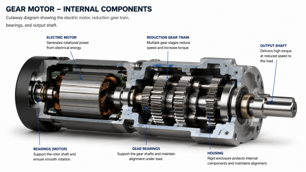
Despite the range of sizes and brands, every gear motor contains the same basic components:
Part
What it does
Electric motor
Converts electrical power into rotation at high speed
Input shaft
Carries the motor’s rotation into the gearbox
Pinion / input gear
Small gear that starts the reduction train
Gear train
One or more meshing gear pairs that reduce speed and increase torque
Output shaft
Delivers the slow, high-torque rotation to the machine
Bearings
Support the shafts and keep gears aligned
Housing
Encloses the gears, holds the lubricant, and protects the unit
The motor type and gear arrangement can vary — AC induction, DC, or brushless DC motors, and spur, helical, worm, or planetary gear trains — but the job of every part stays the same. For a full breakdown of gearbox arrangements and their strengths, see our guide on gear reducer types.
How a Gear Motor Works, Step by Step
Electricity enters the motor. The power supply energizes the motor windings and creates a rotating magnetic field.
The rotor turns. The magnetic field drags the rotor around, spinning the input shaft at high speed.
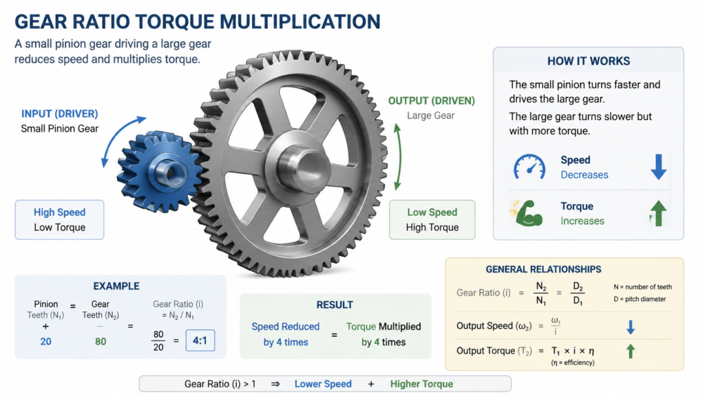
The input gear drives the first gear. The small pinion on the input shaft meshes with a larger gear. Because the larger gear has more teeth, it turns more slowly — and with more force.
Power passes through the gear train. In multi-stage units, each additional gear pair multiplies the reduction. The ratio of the whole train is the product of every stage.
The output shaft delivers the motion. The final gear turns the output shaft at the reduced speed and the multiplied torque, ready to drive the machine.
So the working principle is continuous: fast rotation in, slow rotation out, with torque rising in the same proportion the speed falls.
How the Gear Ratio Converts Speed Into Torque
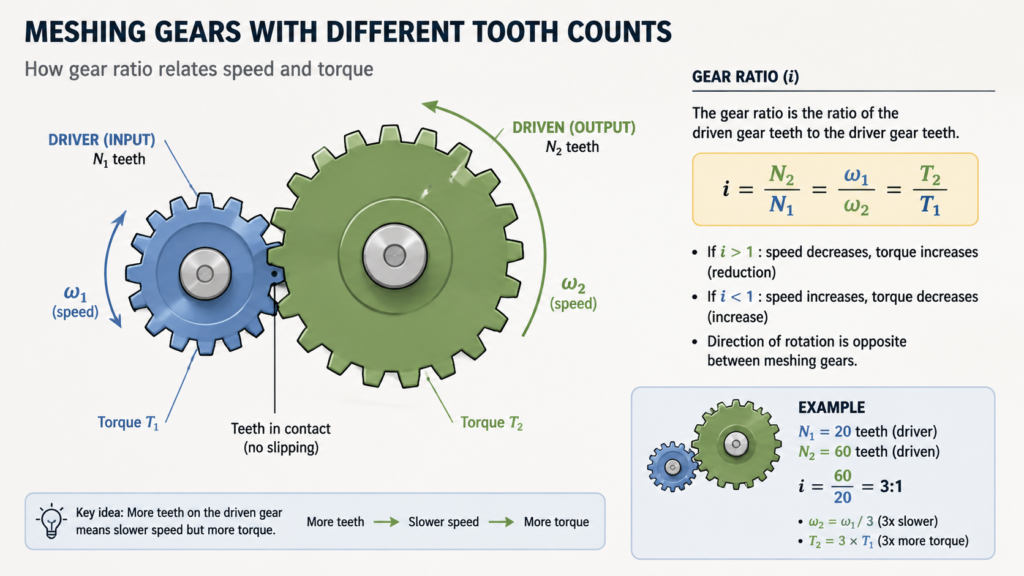
The heart of the mechanism is the gear ratio. When two gears mesh, their rotational speeds are inversely proportional to their numbers of teeth. A small gear with 10 teeth driving a gear with 30 teeth turns the big gear three times slower — a 3:1 ratio — while multiplying torque by three. Add more stages and the ratios multiply together: two 5:1 stages give a 25:1 overall reduction.
Here is how the numbers play out for a 1,500 rpm motor at common ratios:
গিয়ার অনুপাত
Output speed (approx.)
Typical use
3:1
500 rpm
Light blenders, small fans
10:1
১৫০ আরপিএম
Small conveyors, rotary tables
30:1
50 rpm
Standard conveyors, feeders
60:1
25 rpm
Heavy mixers, screw conveyors
100:1
15 rpm
Hoists, slow positioning drives
This torque multiplication is why a compact unit can do the work of a much larger direct-drive motor. The purpose of a gear reduction motor is exactly this transformation — read more about the purposes of a gear reduction motor.
What Happens Inside the Gearbox: Stages and Gear Types
A gear motor can use one gear pair or several. A single-stage unit has one pinion-and-gear set, good for moderate ratios up to roughly 10:1 in one step. To reach higher ratios without making the gears enormous, manufacturers stack stages — a common design in small AC gear motors is a two- or three-stage train that fits a large ratio into a small housing.
The gear type changes efficiency, noise, and how the shaft is oriented:
Spur gears are simple and economical, used in compact light-duty drives.
Helical gears engage more smoothly, giving higher efficiency and quieter operation for continuous-duty machines.
Worm gears achieve a big reduction in one right-angle stage, useful where space is tight.
Planetary gears deliver high torque density in a compact coaxial package, common in servo and mobile equipment.
This is why gear motors are also grouped by motor technology and shaft layout. If you are choosing between configurations, start with your machine’s speed, torque, duty cycle, and mounting space.
Why the Output Is Never Exactly “Ratio × Torque”
Ideal calculations assume no losses. Real gearboxes waste some energy to friction, tooth meshing, oil churning, and bearing drag. Gearbox efficiency varies widely by type: a helical stage typically runs above 95%, while a worm gear unit may sit between 50% and 80%. So the actual output torque is:
Output torque = input torque × gear ratio × efficiency
For a 10:1 gearbox with 90% efficiency, you get about 9 times the torque, not 10. Because of these losses, a gear motor also cannot create power — the output power is slightly less than the input power. The trade-off is always speed for torque, never extra energy.
Common Questions About How Gear Motors Work
Does a gear motor increase power?
No. The gearbox exchanges speed for torque. Output power is always a little lower than input power because of friction and other losses.
Why does a gear motor produce more torque at lower speed?
Meshing gears multiply force by the ratio of their teeth. Slower output means the force is spread out over a longer time per revolution, which appears as higher torque at the shaft.
গিয়ার মোটর এবং গিয়ারবক্সের মধ্যে পার্থক্য কী?
A gearbox is just the gear assembly. A gear motor integrates that gearbox with an electric motor as one matched drive unit.
How many gear stages does a gear motor have?
From one to several. Higher overall ratios usually need more stages so the gears stay a reasonable size and fit in the housing.
Can a gear motor run in reverse?
Many can, but it depends on the motor, gearbox design, and brake. Confirm the permitted direction and switching frequency with the supplier before use.
How do I know which gear ratio I need?
Divide the motor’s rated speed by the required output speed for a first estimate, then verify torque, efficiency, duty cycle, and the manufacturer’s available ratios.
The Practical Takeaway
A gear motor is a fast electric motor and a speed-reducing gearbox built as one unit. Inside, meshing gears slow the rotation and multiply the torque, converting the motor’s high-speed power into the slow, strong motion that real machinery needs. The gear ratio sets the balance, and efficiency losses mean the real output is always a little below the ideal calculation.
Practical guide to selecting a gear motor for door openers: calculate required torque and output speed, understand self-locking worm gear drives, and match the right AC gear motor to your door type.
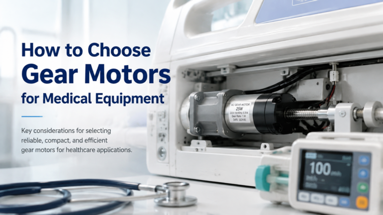
Selection guide for gear motors used in hospital beds, infusion pumps, ventilators, lab equipment and other medical devices. Covers noise, precision, IEC 60601-1 safety, IP rating and self-locking requirements, plus a step-by-step selection workflow and application table.
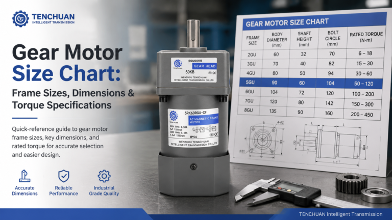
Read a practical gear motor size chart for small AC gear motors. Frame sizes 60-104 mm, dimensions, rated torque and RPM at common ratios, mounting styles.