সমান্তরাল শ্যাফট বনাম রাইট-অ্যাঙ্গেল গিয়ার মোটর: কোনটি আপনার মেশিনের জন্য উপযুক্ত?
রাইট-অ্যাঙ্গেল বনাম ইনলাইন গিয়ার মোটর: বাস্তব অনুমোদিত লোড টেবিলের তুলনায় দক্ষতা, টর্ক, স্ব-লকিংয়ের মিথ এবং পাঁচ ধাপে কীভাবে সিদ্ধান্ত নেবেন।.
আরও পড়ুন
Almost every article about door opener gear motors repeats the same claim: use a worm gearbox, because worm drives are self-locking. That advice is correct in principle and misleading in practice, for two reasons. First, self-locking in a worm drive depends entirely on the lead angle and the friction state — high-efficiency worm boxes with a small lead angle are না reliably self-locking under vibration, and many door operators use exactly those. Second, if you are sizing a compact right-angle AC gear motor with a spur or bevel final stage, the gearbox is না self-locking at all, and any selection process that assumes it will produce a door that creeps, drops or can be pushed open.
This guide works through door opener selection the way it should be done: three numbers for the drive, then a separate decision about how the door is held when the power goes off.
A bare motor spins too fast and produces too little torque to move a door panel directly. The gearbox does two jobs at once: it reduces output speed to roughly 10–120 r/min where door mechanisms work, and it multiplies torque by roughly the ratio. On top of that, door openers add four requirements that a conveyor drive does not have:
Only the third item concerns the gear train, and there is more than one way to solve it.
Torque selection starts with the resistance the drive must overcome, not with the motor nameplate. For a linear drive (rack-and-pinion or belt), the required output torque is:
Tবাইরে = F × r ÷ ηdrive
where F is the total door resistance force in newtons (seal drag, track friction, weight distribution, wind), r is the pinion or pulley radius in metres, and ηdrive is transmission efficiency between gearbox and door — about 0.9 for a clean rack or belt drive, 0.7–0.8 for a worn or fouled track.
For a swing door driven at the hinge, the torque is a moment rather than a force:
Thinge = m · g · d · cosθ + Tcloser
with m the leaf mass, d the horizontal distance from hinge to centre of mass, θ the opening angle and Tcloser the spring torque added by the door closer. The closer spring is the term most often forgotten — on a standard overhead closer it can add 30–50% to the required drive torque through the middle of the travel.
Reference figures for indoor doors: running resistance of a sliding panel with new seals is roughly 50–100 N. Sizing on that running value is a mistake, because peak load occurs at breakaway. Apply a service factor of 1.5–2.0 to the breakaway figure.
Door opening time is specified, not optional. A 1.2 m wide sliding door that must open in 1.5 s at a pulley radius of 40 mm needs a belt speed of 0.8 m/s, which gives 191 r/min at the pulley — then divide by the pulley-to-gearbox ratio. In practice, sliding operators land at 100–250 r/min at the gearbox output; swing and gate operators at 10–60 r/min because the hinge ratio is much larger.
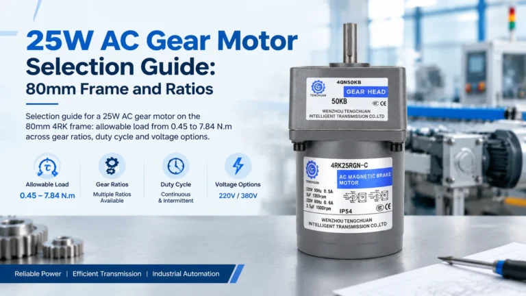
Once you have output speed, read allowable load at that ratio rather than inferring torque from motor power. On the 25 W 4GN right-angle series (80 mm frame), the real numbers are:
| অনুপাত | Output speed (rpm, 50 Hz) | সর্বোচ্চ অনুমোদিত লোড |
|---|---|---|
| 3:1 | 500 | ০.৪৫ নিউটন-মিটার |
| 10:1 | 150 | ১.৫৫ নিউটন-মিটার |
| 30:1 | 50 | ৪.১২ নিউটন-মিটার |
| 50:1 | 30 | 6.18 N·m |
| 100:1 | 15 | ৭.৮৪ নিউটন-মিটার |
For a light indoor swing door or a small gate, 25 W at 50:1 gives 6.18 N·m at 30 r/min, which covers a broad class of pedestrian doors. Heavier or wider leaves move to a 40–90 W unit; vehicle barriers and large industrial gates belong to the 120–300 W range.
There are four legitimate ways to hold a door, and only one of them is the gearbox.
Worm drives become self-locking when the lead angle is below the friction angle — roughly below 5°, which in practice means ratios above about 40:1 with a single-start worm. Two caveats matter:
If you use a worm box for holding, treat self-locking as a secondary safety and still provide a mechanical stop or brake for the primary hold.
A spring-applied, power-released brake holds the shaft when the supply drops. It is definitive and independent of gear geometry. Cost adder is modest, and it works with any gear type — spur, helical or bevel. This is the normal specification for any vertical or inclined axis, and for gates that must not be pushed open.
For end-of-travel holding — a closed door resting against its jamb, a barrier arm sitting on its stop — the structure holds the load, not the drive. This is free and completely reliable, and it is what most sliding door operators actually rely on. The drive only has to reach the stop, not hold position mid-travel.
On overhead and sectional doors, springs carry the leaf weight so the drive only overcomes friction and imbalance. A correctly balanced door with a non-self-locking gear train will sit still because there is no net load. Verify the balance, and provide a brake or stop as a backstop for spring failure.
The takeaway: a spur or bevel right-angle AC gear motor is না self-locking. If your door must hold position without a worm box, you need a brake, a mechanical stop, or a counterbalance. Do not specify “self-locking” as a gear motor requirement unless the gear type actually provides it.
Door operators are intermittent-duty machines, which usually suits a reversible 30-minute-rated AC gear motor well — a busy shop entrance at 60 cycles per hour still leaves the motor unpowered most of the time. Two cautions:
Power selection follows the frame, not the other way round: a 25 W unit on an 80 mm frame is single-phase 110V/220V or three-phase 220V; 400 W and above on the medium frames are three-phase 220V/380V. If the site only has single-phase supply, that constrains you to the small frames and therefore to door sizes the small frames can move.
Not if the final stage is a bevel or spur gear. Self-locking requires a worm gear with a lead angle below the friction angle. A compact right-angle bevel unit will back-drive under load.
Most sliding operators want 100–250 r/min at the gearbox output. With a 4GN 25 W unit, that is a 3:1 to 10:1 ratio — but at 3:1 the allowable load is only 0.45 N·m, so verify the door resistance before choosing the shallowest ratio.
Yes for light indoor pedestrian leaves where the hinge ratio is favourable, typically with 30:1 to 50:1 giving 4–6 N·m at 30–50 r/min. Heavier leaves, wind-exposed locations and doors with strong closers need 40–90 W.
A friction brake is not enough. Use a mechanical latch, a brake with sufficient holding torque, or a self-locking worm stage, and specify the holding torque against the forcing load rather than the door weight.