গিয়ার মোটরগুলির ধরন: স্পুর, হেলিক্যাল, ওর্ম, বেভেল ও প্ল্যানেটারির সম্পূর্ণ গাইড
প্রকাশিত: লেখক: লিসা
A gear motor packages an electric motor and a gearbox into one unit, trading raw motor speed for usable torque at the output shaft. But the gearbox inside is not a generic part—its gear geometry decides how much torque the drive delivers, how quietly it runs, how efficient it is, and even whether it can hold a load in place when the power cuts out. Understanding the main gear motor types is therefore the first step in any drive selection, whether you are building a conveyor, an automatic door, or a packaging line.
This guide covers the five fundamental gear motor types—spur, helical, worm, bevel, and planetary—how each one works, where each excels, and how to match the right type to your application.
What Is a Gear Motor?
A gear motor is a motor and a gear reducer combined in a single housing. The motor—typically an AC induction motor or a brushed/brushless DC motor—spins at its native speed, often 1,000–3,000 RPM, which is far too fast for most driven equipment. The gearbox reduces that speed through gear meshes, and in exchange multiplies the torque. A motor running at 1,500 RPM paired with a 50:1 gearbox delivers about 30 RPM at roughly 50 times the torque, minus efficiency losses.
Integrating the two components into one assembly eliminates shaft-alignment problems, shortens installation time, and simplifies ordering—one part number instead of two. If you are new to the concept, it helps to first understand how a gear motor works before comparing gear types.
The 5 Main Types of Gear Motors
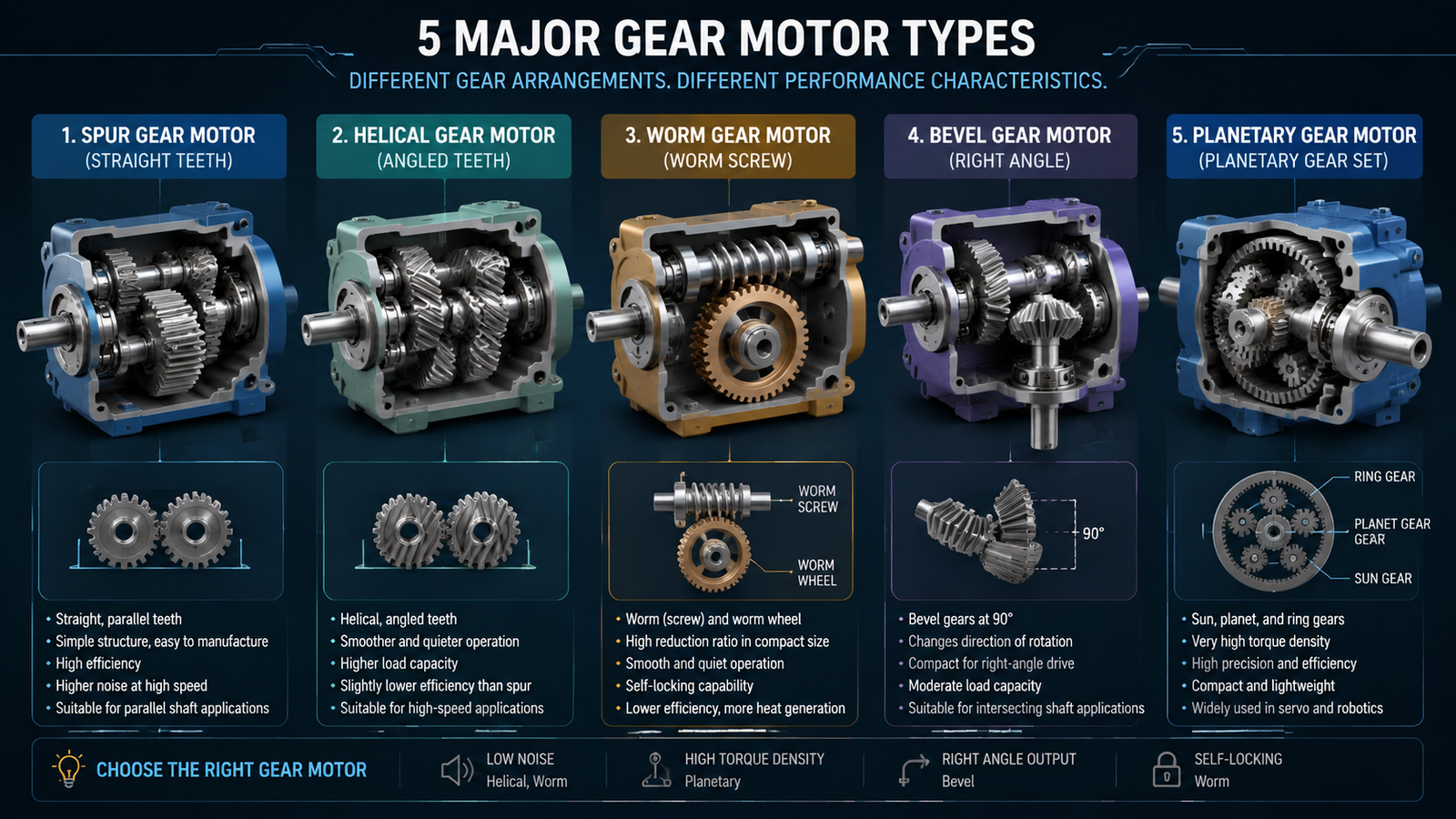
Engineers classify gear motors by the gear arrangement inside the reducer. Five designs dominate the market: spur, helical, worm, bevel, and planetary. Each has a distinct tooth geometry and shaft layout, and those differences drive every practical trade-off that follows.
Spur Gear Motors
Spur gear motors use gears with straight-cut teeth mounted on parallel shafts. It is the oldest and simplest gear design, and that simplicity is its strength: manufacturing is easy, costs are low, and efficiency per stage is excellent at 95–98%.
The drawback is noise. Because the full face width of each tooth engages at once, tooth-to-tooth impacts produce a characteristic whine that grows with speed and load. Single-stage ratios are usually limited to about 2:1–10:1, so large reductions need multiple stages, which erodes the efficiency advantage. Spur gear motors suit low-to-moderate speed applications where cost matters more than quiet operation—conveyors, vending mechanisms, appliances, and light machinery.
Helical Gear Motors
Helical gear motors cut their teeth at an angle to the shaft axis. Angled teeth engage progressively rather than all at once, so contact builds and releases smoothly across the tooth face. The result is quieter running, less vibration, and higher load capacity than an equivalent spur set, with stage efficiency typically between 96% and 99%—often the highest of any gear type.
The angled tooth profile generates axial thrust along the shaft, so the gearbox needs thrust bearings and a housing designed to carry that load. Helical gear motors are the default choice in continuous-duty industrial drives: mixers, pumps, fans, packaging machinery, and elevators, where a combination of efficiency and low noise pays off over thousands of operating hours.
Worm Gear Motors
A worm gear motor pairs a screw-like worm on the motor shaft with a toothed worm wheel. The two shafts sit at 90° to each other, giving a compact right-angle drive that achieves very high single-stage ratios—from 5:1 up to 100:1 in some designs.
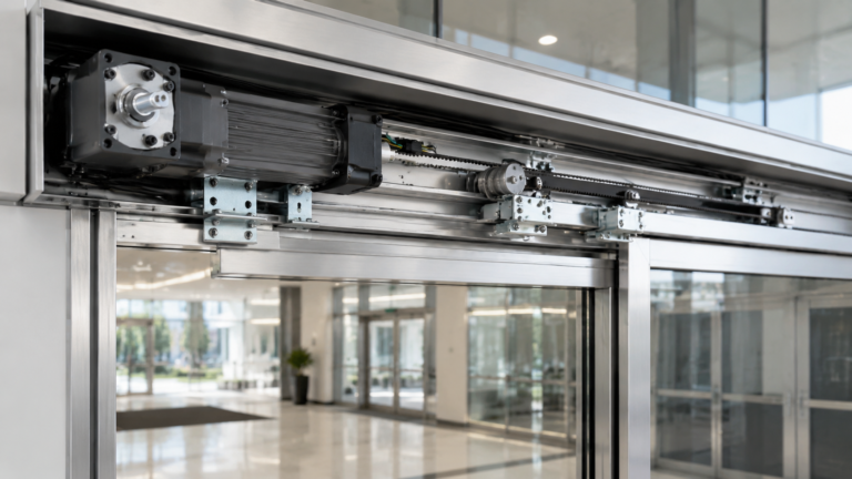
Worm drives have two defining characteristics. First, the sliding contact between worm and wheel generates heat and keeps efficiency modest, typically 40–70%. Second, at ratios above roughly 20:1 the set becomes self-locking: the load cannot back-drive the motor, so a gate, valve, or hoist holds its position without a brake. That single property explains why worm gear motors dominate door openers, gates, lifts, winches, and valve actuators. For a deeper look at terminology, see this comparison of a gear reduction motor vs gear motor.
Bevel Gear Motors
Bevel gear motors use conical gears to transmit motion between shafts that intersect, usually at 90°. Where a worm drive turns the corner with a screw, a bevel set does it with meshing cone-shaped gears—available as straight-tooth (simpler, noisier) or spiral-tooth (smoother, quieter, higher capacity) versions.
Single-stage bevel ratios are modest, commonly 1:1–6:1, so reducers with higher ratios pair a bevel first stage with helical or spur stages behind it. Stage efficiency of 93–97% is better than worm gearing, and bevel drives handle higher speeds than worm sets. They appear wherever the output shaft must exit perpendicular to the motor: agitators, rotary tables, corner conveyor transfers, and agricultural equipment.
Planetary Gear Motors
Planetary gear motors—also called epicyclic drives—arrange multiple planet gears around a central sun gear, all meshing inside an outer ring gear. The load splits across several gear meshes simultaneously, which gives planetary drives the highest torque density of the five types: often 3–5 times the torque of a same-diameter spur gearbox.
The coaxial layout puts the input and output on the same axis, saving length in tight installations. Stage efficiency runs 90–97%, ratios reach about 3:1–10:1 per stage with multiple stages stacked for more, and backlash can be held very low in precision versions. The trade-off is complexity—more components, tighter tolerances, and usually a higher price. Planetary gear motors power robotics joints, precision actuators, medical devices, electric tools, and servo applications.
Gear Motor Types at a Glance
The table below condenses the five designs into the numbers that matter most during selection.
Type
Efficiency / Stage
Typical Ratio
Noise
Self-Locking
Shaft Layout
উদ্দীপক
95–98%
2:1 – 10:1
Moderate–high
No
Parallel
ঘূর্ণীয়মান
96–99%
1.5:1 – 10:1
Low
No
Parallel
কৃমি
40–70%
5:1 – 100:1
Low
Yes (>20:1)
Right angle
Bevel
93–97%
1:1 – 6:1
Low–moderate
No
Right angle
গ্রহীয়
90–97%
3:1 – 10:1
Low–moderate
No
Coaxial
How to Choose the Right Gear Motor Type
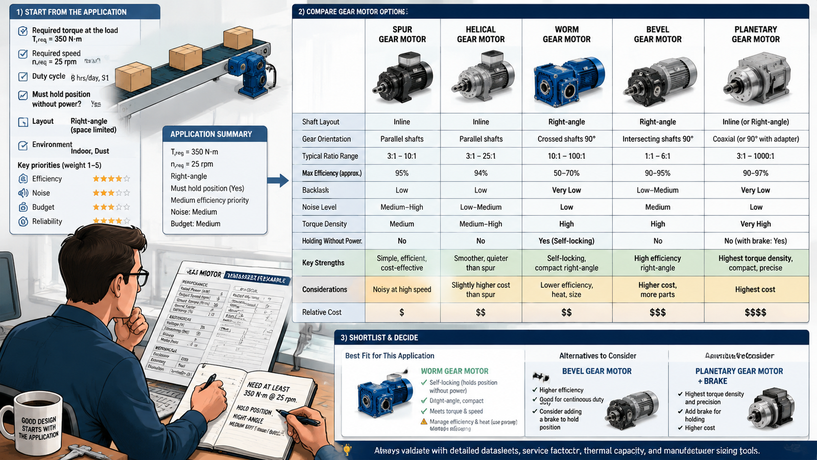
Start from the application, not the catalog. Ask four questions in order:
What torque and speed does the load actually need? Calculate required torque at the output shaft, including startup and shock loads, and target output speed. These two numbers eliminate most types immediately.
Must the drive hold position without power? If yes—gates, hoists, tilt platforms—a self-locking worm gear motor is usually the simplest answer, avoiding the cost of a brake.
Does the layout need a right-angle or inline output? Right-angle worm and bevel drives fit where an inline motor would stick out into walkways or machinery; inline and coaxial drives align better with conveyors and pumps.
How sensitive are efficiency, noise, and budget? Continuous-duty equipment rewards helical efficiency; intermittent-duty access equipment tolerates worm losses; precision motion justifies planetary cost.
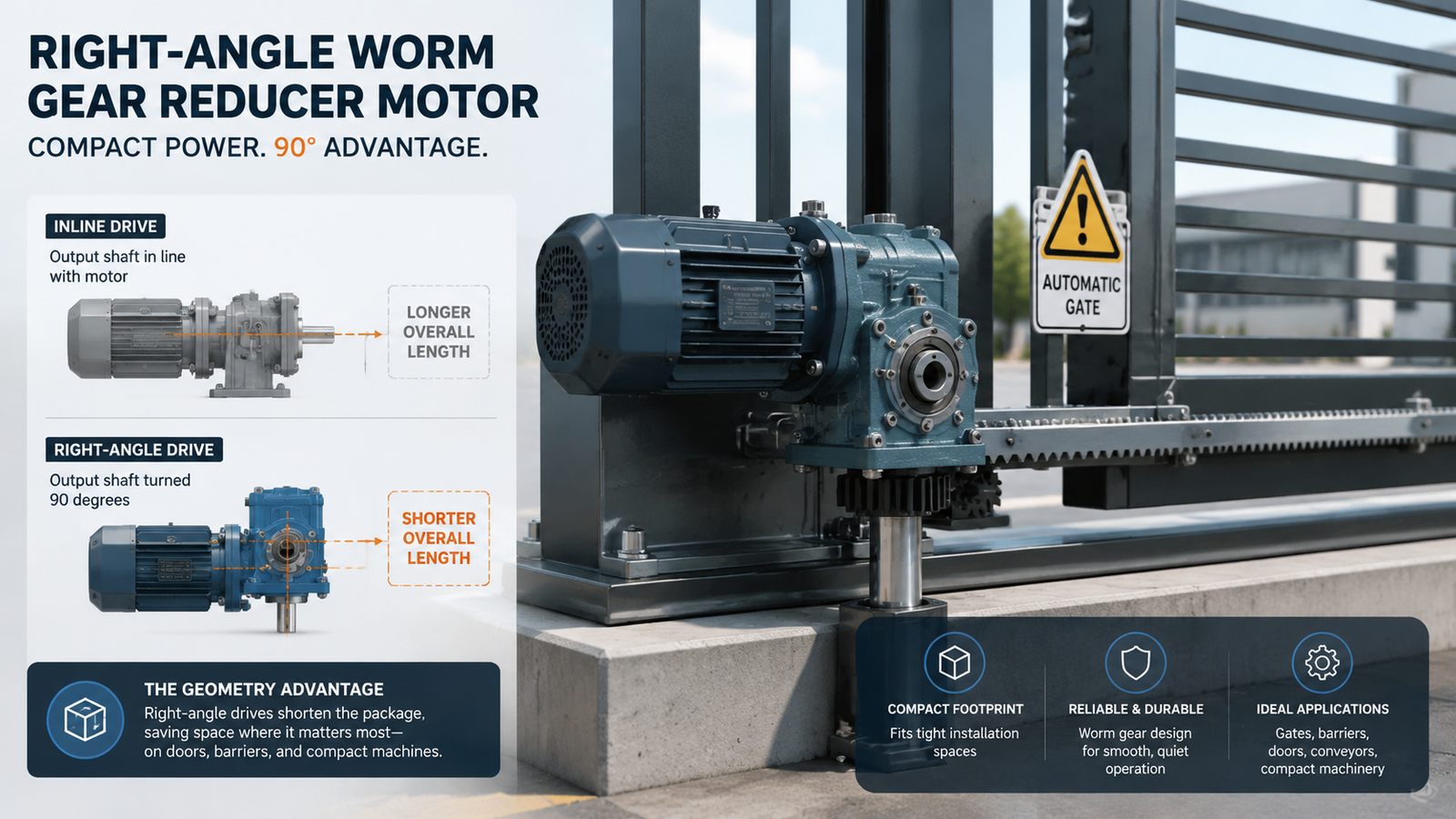
Shaft layout is often the deciding factor in real installations, and it cuts across the type list: spur, helical, and planetary drives are inline or coaxial; worm and bevel drives are right-angle.
Inline drives keep the output shaft in line with the motor, which suits conveyors, pumps, and mixers where the driven shaft is already oriented along the machine. They are generally the more efficient path. Right-angle drives turn the output 90°, which shortens the total package dramatically—a right-angle gear motor can tuck a 300 W drive into a space an inline motor alone would fill. On doors, barriers, and compact machines, that geometry advantage outweighs the efficiency gap. It is also worth understanding why an electric motor should use a speed reducer gearbox before deciding how much reduction you need in the first place.
Common Gear Motor Selection Mistakes
Sizing on running torque only. Startup and shock loads routinely exceed running torque by 2–3×. A drive that survives steady-state can stall or strip teeth on every cold start.
Ignoring duty cycle on worm drives. Continuous operation at a 40–70% efficiency rating turns the lost power into heat. In enclosed or high-ambient installations, thermal capacity—not torque—becomes the real limit.
Assuming more ratio is always better. Excessive reduction wastes efficiency at every stage and multiplies backlash. Specify the ratio your load needs, not the largest available.
Overlooking noise requirements. A spur drive that is fine on a factory conveyor is unacceptable in a medical device or a quiet office door. Helical or worm designs cost little more and cut the noise substantially.
Forgetting self-locking when it matters. Retrofitting a brake onto a non-locking drive is far more expensive than selecting a worm gear motor at the start.
Conclusion: Match the Gear Type to the Job
Spur gear motors win on cost and simplicity, helical on efficiency and quiet running, worm on right-angle layout and self-locking hold, bevel on efficient 90° power transmission, and planetary on torque density and precision. None is universally best—the right answer comes from your load, your layout, and your duty cycle.
Once you have a shortlist of types, the next step is translating it into a specific power and ratio. Start with a review of গিয়ার রিডাক্সার মোটর কীভাবে কাজ করে to see how these gear types behave inside a complete AC gear motor assembly.
প্রায়শই জিজ্ঞাসিত প্রশ্নাবলী
Which type of gear motor is most common?
Helical gear motors are the most common in industrial fixed-speed applications because they combine high efficiency with low noise and high load capacity. For small right-angle applications such as doors and gates, worm gear motors are the dominant choice.
Which gear motor type is the most efficient?
Helical gearing is typically the most efficient at 96–99% per stage, slightly ahead of spur gearing. Worm gearing is the least efficient at 40–70% due to sliding contact, which is also why worm drives need more attention to heat dissipation.
When do you need a self-locking gear motor?
Whenever a load must hold its position without power—gates, doors, window openers, hoists, tilt tables, and valve actuators. Worm gear motors above roughly 20:1 ratio are self-locking by design, so the load cannot spin the motor backwards.
Which gear motor is the quietest?
Helical and worm gear motors run quietest, because their tooth engagement is gradual or sliding rather than impact-based. Spur gears are the noisiest, especially at higher speeds.
Can one gear motor type replace another?
Sometimes, if torque, speed, and ratio requirements overlap, but the shaft layout and self-locking behavior usually decide. A planetary drive cannot replace a worm drive on a gate that must hold position, and an inline drive cannot replace a right-angle drive in a compact machine frame.
What is the difference between inline and right-angle gear motors?
Inline (parallel or coaxial) gear motors put the output shaft in line with the motor; right-angle gear motors turn the output 90° using worm or bevel gearing. Inline drives are generally more efficient, while right-angle drives save space and, with worm gearing, can hold loads without a brake.
Practical guide to selecting a gear motor for door openers: calculate required torque and output speed, understand self-locking worm gear drives, and match the right AC gear motor to your door type.
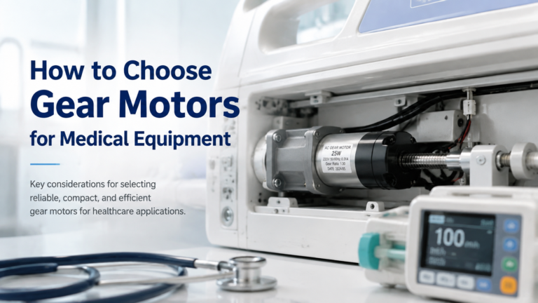
Selection guide for gear motors used in hospital beds, infusion pumps, ventilators, lab equipment and other medical devices. Covers noise, precision, IEC 60601-1 safety, IP rating and self-locking requirements, plus a step-by-step selection workflow and application table.
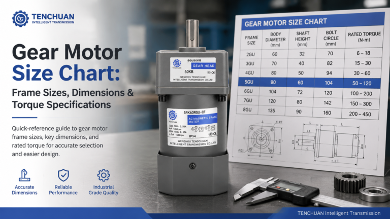
Read a practical gear motor size chart for small AC gear motors. Frame sizes 60-104 mm, dimensions, rated torque and RPM at common ratios, mounting styles.