How to Select a Gear Motor for Door Openers: Torque, Speed & Self-Locking Requirements
Ngày đăng: Tác giả: Lisa
Choosing a gear motor for door openers comes down to three numbers: how much torque the drive must deliver to move the door, how fast the output shaft has to turn so the door opens in the right time, and whether the gear train can hold the door in position when the motor is off. Door opener mechanisms—automatic sliding entrances, swing doors, overhead panels and gate operators—all follow the same logic, and most are driven by a compact động cơ giảm tốc bánh răng góc vuông with a worm final stage. This guide explains the torque, speed and self-locking requirements behind that choice, walks through a worked example, and shows which AC gear motor power tier fits common door opener loads.
What a door opener asks from a gear motor
A bare motor spins too fast and produces too little torque to move a door panel directly. The gearbox does two jobs at once: it reduces output speed to roughly 20–120 rpm where door mechanisms actually work, and it multiplies torque by roughly the gear ratio. But door openers add requirements that ordinary conveyor drives do not:
High breakaway torque. The hardest part of every cycle is the first movement—overcoming weather seals, gaskets, track friction and any accumulated dirt.
Frequent starts and reversals. A door operator is an intermittent-duty machine that starts, stops and reverses dozens to hundreds of times per day.
Position holding. When power is removed, the door must stay where it is instead of creeping, dropping or being pushed open.
Quiet, compact running. Door operators live in occupied spaces and often mount inside a slim header or jamb.
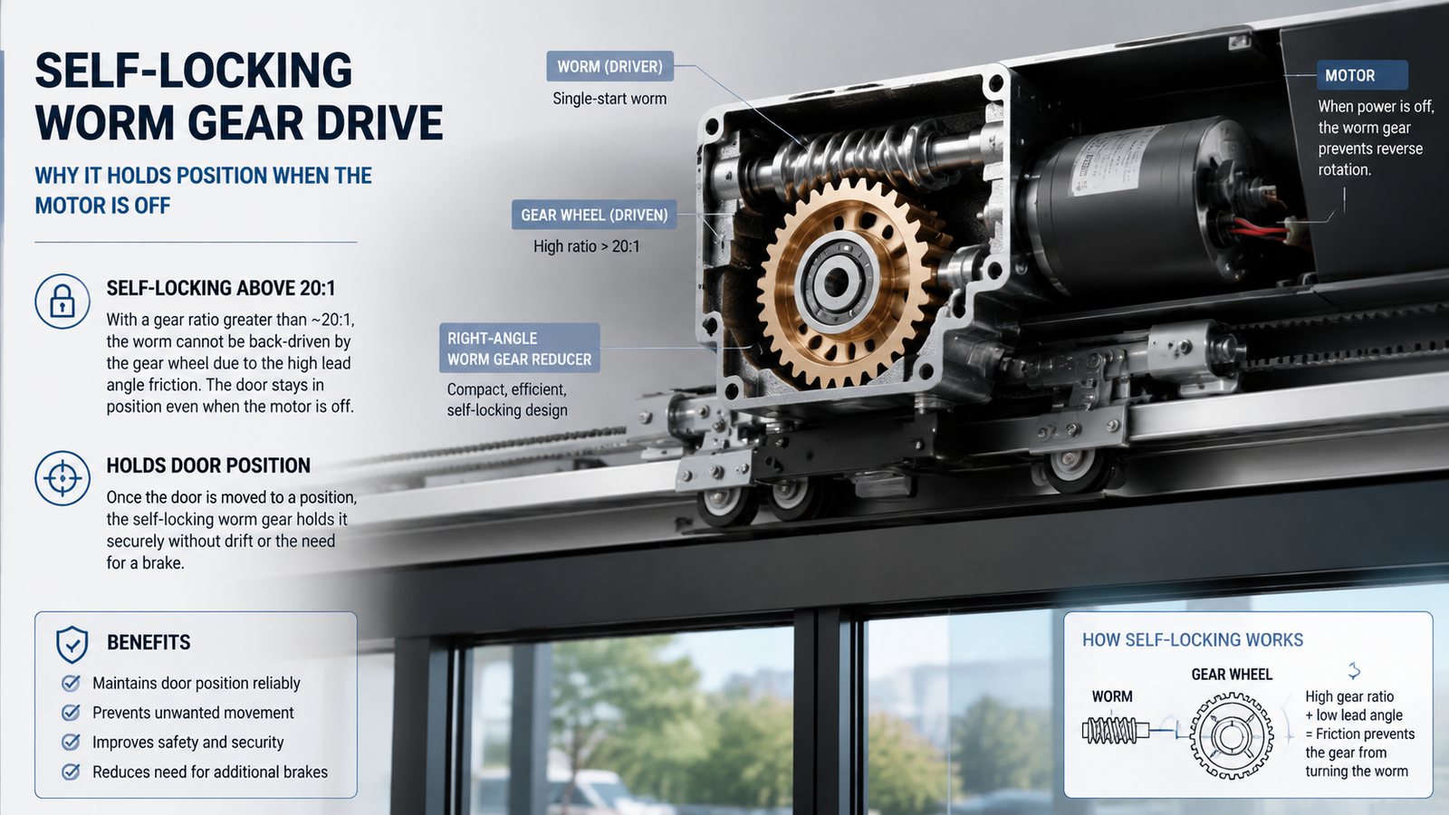
These demands point to a gearmotor with a worm gear final stage: worm drives are compact, naturally quiet at low speed, and —above a certain ratio—inherently self-locking.
Step 1: Calculate the torque your door actually needs
Torque selection starts with the resistance the drive must overcome, not with the motor nameplate. For a linear drive (rack-and-pinion or belt), the required output torque is:
Tout = F × r ÷ ηdrive
where F is the total door resistance force (door weight distribution, seal drag, track friction and wind, in newtons), r is the pinion or pulley radius in metres, and ηdrive is the efficiency of the transmission between gearbox and door (about 0.9 for a clean rack or belt drive).
As a reference point, the running resistance of a typical indoor automatic sliding door panel is roughly 50–100 N when seals are new. Sizing on the running value is a mistake: the peak load occurs at breakaway, so apply a service factor of 1.3–1.5 on the worst-case value to cover ageing seals, temperature changes and wind on semi-exposed doors.
Ví dụ minh họa. A sliding door with a worst-case resistance of 100 N driven through a pinion of 0.04 m radius needs a running torque of 100 × 0.04 ÷ 0.9 ≈ 4.4 N·m. With a 1.5 service factor, the gearmotor output should be rated for about 6.6 N·m at minimum.
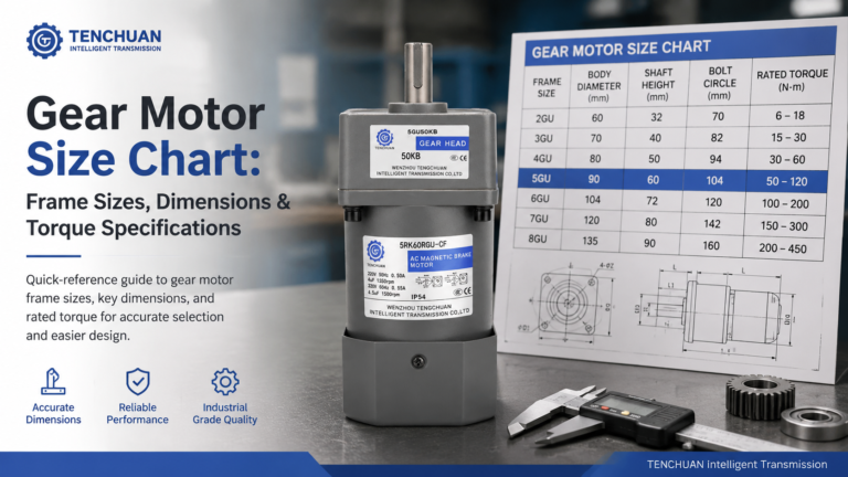
Once you know the torque, compare it against the rated torque of candidate units at the speed you need. Gearmotor torque falls as output speed rises, so always check the torque curve at the operating point, not the stall value. This is where a gear motor size chart with frame sizes, dimensions and torque specifications becomes useful for shortlisting candidates.
Step 2: Set output speed and pick the gear ratio
Door opening time decides output speed. For a sliding or gate drive, first convert the desired linear travel speed into output rpm:
nout = (v × 60) ÷ (2π × r)
where v is the door travel speed in m/s and r is the pinion or pulley radius in metres. A 0.4 m/s travel speed on a 0.04 m pinion gives nout ≈ 95 rpm. The gear ratio is then simply the motor rated speed divided by the required output speed:
i = nmotor ÷ nout
With a 1400 rpm AC induction motor and a 95 rpm requirement, i ≈ 14.7, so a standard 15:1 unit fits; choosing 20:1 would raise torque and improve the self-locking margin while slowing the door to roughly 0.3 m/s. There is always this trade-off between speed, torque and self-locking strength, which is why it is worth understanding how to calculate the gear ratio of a gear reduction motor before locking in a specification.
Step 3: Confirm self-locking behaviour
For most door openers, self-locking is a requirement, not an option. In a worm gear drive above a certain ratio (typically around 20:1 and higher), the worm can rotate the gear wheel but the wheel cannot back-drive the worm. The practical effects for a door operator:
The door holds its position whenever the motor is de-energised—no creep, no gravity drop, no separate brake needed.
The door resists being pushed open from outside, which is both a security and a safety feature for gates and entrance doors.
Limit switches and a simple reversing controller are enough to manage open/close travel.
This is why worm gear motors dominate door opener and gate operator designs. Right-angle AC gear motors use a worm first stage and inherit this behaviour automatically. Two caveats: worm drives are less efficient (roughly 0.5–0.8 depending on ratio and lubrication), so they generate more heat under continuous running—acceptable for intermittent door duty—and if the door must be manually pushable during a power failure for egress, the mechanism needs a manual release clutch or a brake-and-non-self-locking combination instead. For pedestrian automatic doors, also check the applicable force-limit standard in your market (for example EN 16005 in Europe) when specifying the operator.
Step 4: Match power, duty cycle and environment
With torque, speed, ratio and self-locking confirmed, the remaining checks are operational:
Duty cycle. Count realistic cycles per day and the average running time per cycle. Door openers run under S2/S3 intermittent duty with frequent reversals, so the motor needs thermal headroom; a motor that is correctly sized for torque but oversized for duty class will overheat on a busy entrance.
Control. AC gear motors are driven by a capacitor start/run circuit and reversed with a relay, contactor or door controller. Add limit switches for end-of-travel and a thermal protector in the motor winding.
Environment. Indoor headers need standard protection; semi-outdoor gates and garage applications need a motor housing and terminal box rated for dust and moisture, and the gearbox should be checked for its ambient temperature range.
Mounting. Door headers are tight. Right-angle units mount flat against the header or jamb and deliver the output shaft at 90° to the motor, which suits linear drives running along the door track.
Matching a right-angle AC gear motor to your door opener
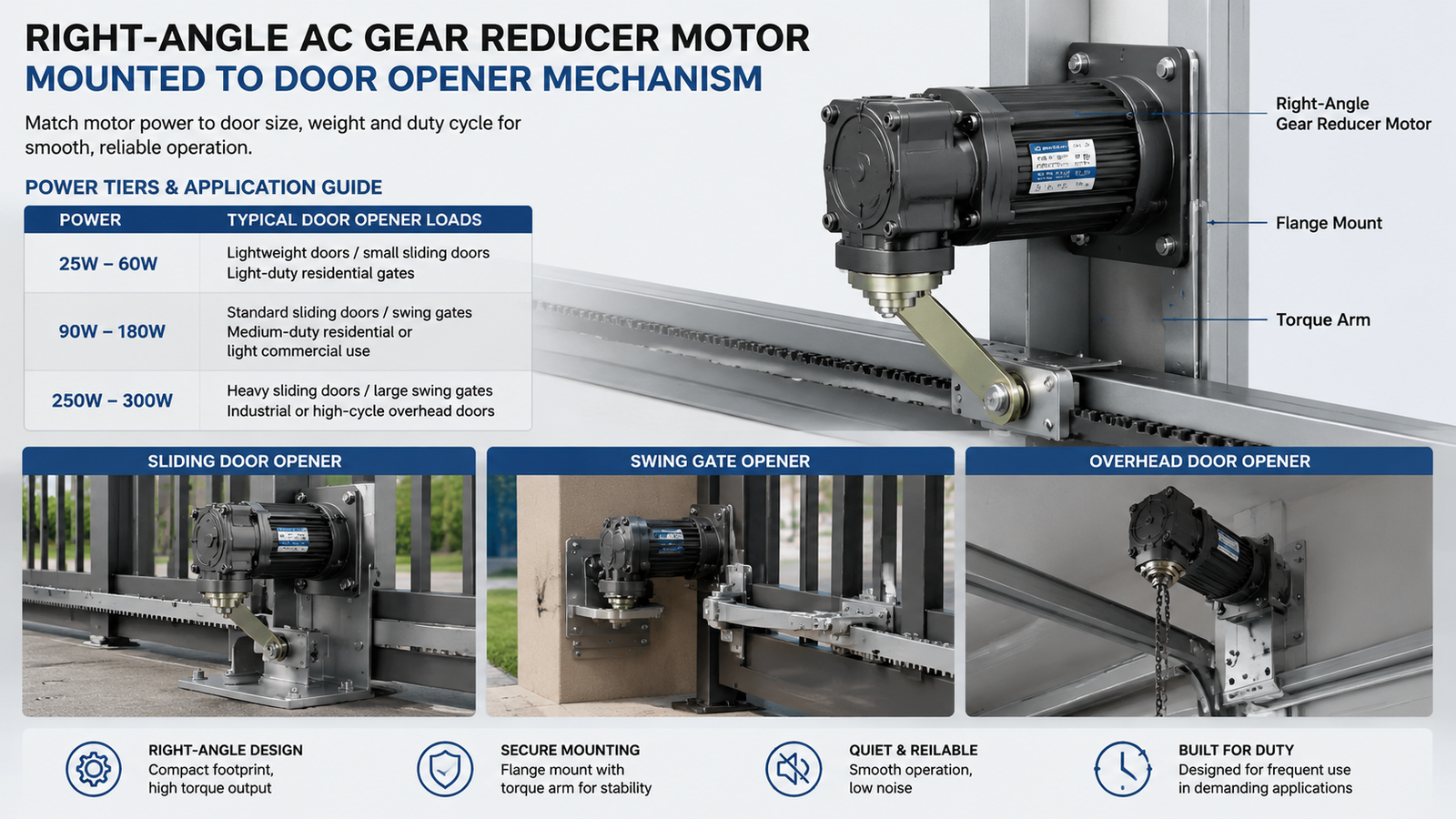
Small and medium right-angle AC gear motors cover most light- and medium-duty door opener builds. Use the tier below as a starting point, then confirm torque and speed against the product data sheet at the operating point you calculated.
Door opener load
Các ứng dụng điển hình
Drive tier
Notes
Light duty, low cycle, indoor
Small sliding or swing entrances, display doors, light gates
For every tier, verify the maximum permissible radial and axial load on the output shaft: door mechanisms often impose side loads that damage undersized bearings even when torque is adequate.
Conclusion
Selecting a gear motor for door openers is a four-step process: define the worst-case door resistance and calculate output torque with a 1.3–1.5 service factor, convert the required door speed into output rpm and choose the gear ratio, confirm that the worm drive self-locks at that ratio, then check duty cycle, control and environment. A right-angle AC gear motor satisfies these requirements in a compact package, which is why it is the workhorse of automatic door and gate operators. If you are sizing a drive and want to compare frame sizes, ratios and torque data side by side, browse the right-angle gear reducer motors range or contact our engineers with your door weight, opening time and cycle count.
Câu hỏi thường gặp
What kind of gear motor is used for door openers?
Most automatic door openers use a right-angle worm gear motor, in AC or DC versions, because the worm drive is compact, quiet at low speed and self-locking. Right-angle AC gear motors are common for mains-powered fixed installations such as sliding and swing entrance doors.
Why does a door opener gear motor need to be self-locking?
Self-locking holds the door in position whenever power is off, so the door cannot creep, drop or be pushed open from outside. This removes the need for a separate holding brake and provides both safety and security for gates, overhead doors and entrances.
How much torque does an automatic door opener motor need?
It depends on door weight, seals and drive radius. A typical indoor sliding panel has a running resistance of roughly 50–100 N; multiply that by the pinion radius and a 1.3–1.5 service factor to get the minimum output torque. Always size on the worst case, not the no-load value.
What gear ratio should a door opener gear motor have?
Divide the motor rated speed by the output speed your door travel time requires. Door opener worm drives commonly use ratios from about 15:1 to 30:1; higher ratios increase output torque and strengthen self-locking but slow the door.
Can a 25W gear motor open an automatic door?
A 25W right-angle AC gear motor can drive light indoor panels and small swing or sliding mechanisms at low cycle counts, provided the torque at the selected ratio meets your calculated requirement. Heavier panels or busy entrances need the 40W–140W or 120W–300W tiers.
AC or DC gear motor for a door opener?
Choose AC when mains power is available and the operator is a fixed installation, which is the common case for building entrance doors; choose DC when battery backup, solar power or low-voltage operation is needed, such as remote gates. Compare the voltage, duty and control options before deciding.
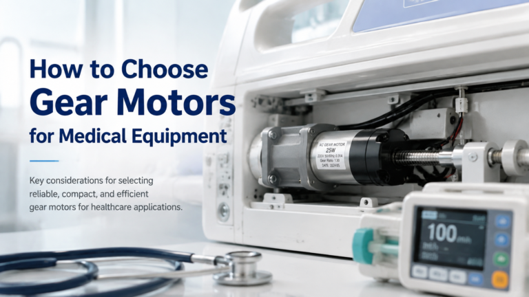
Selection guide for gear motors used in hospital beds, infusion pumps, ventilators, lab equipment and other medical devices. Covers noise, precision, IEC 60601-1 safety, IP rating and self-locking requirements, plus a step-by-step selection workflow and application table.
Read a practical gear motor size chart for small AC gear motors. Frame sizes 60-104 mm, dimensions, rated torque and RPM at common ratios, mounting styles.