Gear Motors for Automatic Doors: Selection Guide & Key Specifications
Ngày đăng: Tác giả: Lisa
Lựa chọn một gear motor for an automatic door comes down to a handful of mechanical specifications: output torque at the door shaft, output speed, duty cycle, and how the drive behaves when power is removed. Get those four numbers right and the rest — voltage, mounting, noise, protection rating — falls into place. This guide explains what each specification means for sliding, swing, folding and revolving door operators, shows typical values by door type, and works through a sizing example so you can shortlist the right automatic door gear motor without guesswork.
How an automatic door drive is built
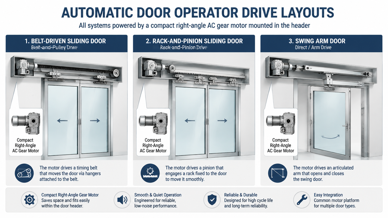
An automatic door operator converts motor rotation into door movement through one of three common transmission layouts. Understanding which one your door uses is the first step, because it defines the output speed and torque the gear motor must deliver.
Belt-and-pulley (sliding doors). The motor drives a small pulley that moves a toothed belt fixed to the door carriage. Door speed is the motor output speed multiplied by the pulley ratio — a small pulley gives more door travel per motor revolution.
Rack-and-pinion (sliding and heavy gates). A gear motor with a pinion engages a rack on the door or gate. This layout is stiffer and better for heavier panels, and it transmits the full gearmotor torque directly.
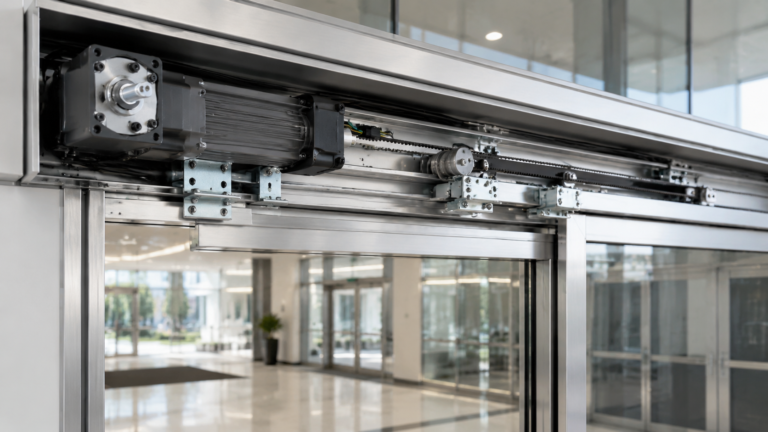
Direct or arm drive (swing, folding, revolving doors). The motor drives the pivot shaft directly or through a short arm/linkage. Torque at the door hinge is what matters, and the gearmotor usually mounts in the header above the door.
In all three layouts the motor itself is typically a small gear reduction motor: high-speed motor plus a reduction stage that multiplies torque and brings output speed down to the 10–100 r/min range a door needs. For a closer look at the drive options behind gate and door automation, our guide to gear motors for door openers walks through the same physics on an operator you can inspect part by part.
Key specifications that decide gear motor selection
Manufacturers list dozens of values, but for automatic doors these seven specifications carry almost all the selection weight.
Specification
What it controls
Typical range for automatic doors
Output torque (N·m)
Whether the motor can start and move the door under worst-case friction, wind and seal load
<55 dB indoors; IP44+ outdoors; 20,000+ h design life
Two specifications deserve extra attention because they are the most common causes of field failure. Torque must be sized for the worst case — cold grease, seal drag, wind load — not the average. And duty cycle must match traffic: a motor rated for 30 minutes of reversible running in a quiet office door will overheat if the operator cycles every few seconds in a busy storefront. If you are comparing models, read how geared DC vs AC motors differ on duty and control before you commit to a voltage family.
Gear motor needs by door type
Door geometry changes the load so much that the same motor family covers very different applications depending on ratio and power. The table below summarises realistic starting points for each door type.
Door type
Typical panel weight
Door speed
Suggested output torque
Suggested motor power
Light interior sliding door
30–80 kg
0.4–0.8 m/s
2–5 N·m at pulley
25–60 W
Heavy sliding / automatic gate
150–400 kg
0.3–0.5 m/s
10–30 N·m
120–300 W
Swing door (single leaf)
40–100 kg leaf
90° in 3–6 s
10–25 N·m at hinge
60–140 W
Folding door
30–60 kg per leaf
0.5–1.0 m/s
3–8 N·m
40–90 W
Revolving door (light commercial)
200–300 kg total
1.5–4 r/min at door
20–50 N·m
140–300 W
Treat the ranges above as sanity checks, not substitutes for calculation. A door with heavy weather seals, a slope, or wind exposure needs more torque than its weight alone suggests. Where your door sits between “light interior sliding” and “heavy sliding gate” determines whether a compact 25 W unit or a 120–300 W right-angle AC gear motor is the honest choice.
Sizing a sliding-door drive in five numbers
A quick first-pass calculation for a belt-driven sliding door uses five numbers and confirms whether your candidate gear motor has enough margin. Worked example for a 60 kg interior sliding door:
Friction force. Assume rolling friction coefficient of about 0.05 plus seal drag. F ≈ 60 kg × 9.81 × 0.05 ≈ 30 N, plus ~20 N seal/start drag → use ~50 N.
Required torque at the pulley. With a 60 mm pulley radius (0.03 m), T = F × r = 50 × 0.03 = 1.5 N·m. Add 30–50% safety margin → target ~2–2.5 N·m.
Required output speed. For 0.5 m/s door speed on a 0.03 m pulley radius: shaft speed = 0.5 / (2π × 0.03) × 60 ≈ 160 r/min. With a further belt reduction this can drop; if the gearmotor drives the pulley directly, plan for ~100–160 r/min.
Gear ratio. A 1250 r/min motor input needs a ratio of roughly 1250 / 150 ≈ 8:1 to 12:1 for direct drive.
Motor power check. P = T × ω = 2.5 N·m × 15.7 rad/s ≈ 40 W. A 25 W unit is marginal at this speed; a 4GN AC right-angle gear reducer motor at higher ratio (more torque, lower speed) or the next frame up is the safer pick.
The same five numbers apply to swing doors — replace pulley radius with the hinge-to-push-point distance, and door travel with opening angle. If ratios and torque conversions are new to you, our guide on how to calculate the gear ratio of a gear reduction motor shows the formulas step by step.
AC right-angle gear motors in automatic door systems
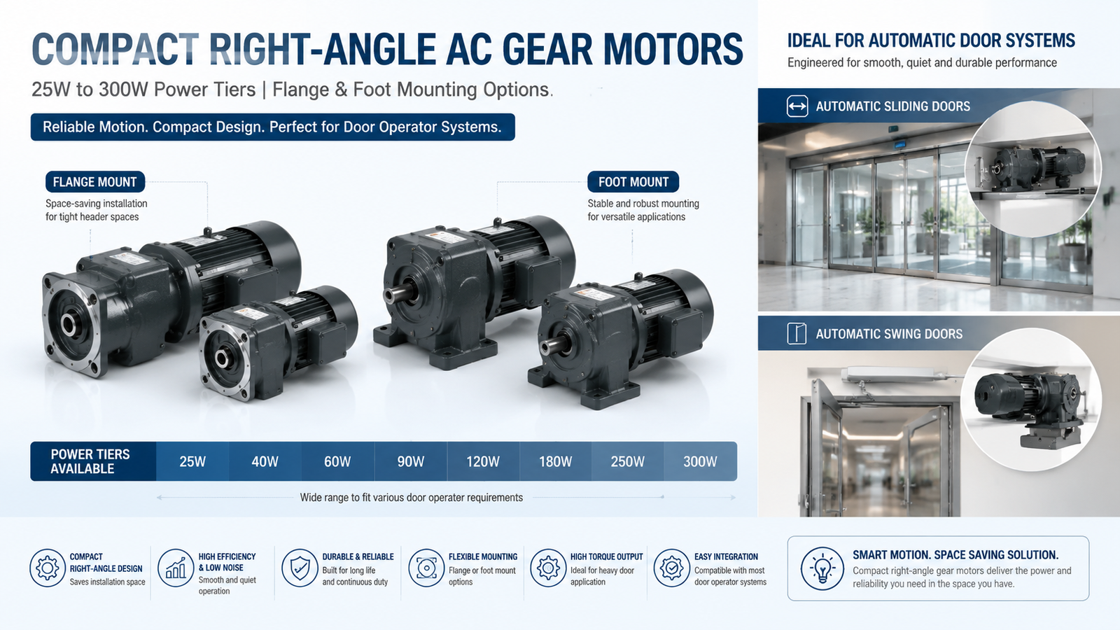
DC motors dominate premium automatic doors because speed control is easy. But AC gear motors remain a practical, low-cost choice for many operators, and the right-angle (worm or hypoid) layout is particularly well suited to door headers, where the motor axis must sit across the door while the output shaft runs along the travel direction.
A typical small AC right-angle unit — such as the 4GN AC right-angle gear reducer motor 25 W — offers single-phase 110 V or 220 V operation, reversible 30-minute duty, output speeds from 5 to 500 r/min through gear ratios of 3:1 to 300:1, and maximum allowable load up to about 7.8 N·m at high ratios. Those numbers cover light sliding doors, small swing-door operators and low-cycle applications. For heavier panels and continuous traffic, step up to the 5GU AC right-angle gear reducer motor 40–140 W hoặc 6GU series 120–300 W with the same compact right-angle footprint.
Two fit notes for AC drives in automatic doors. First, if the operator must hold the door against manual push or gravity when idle, choose a self-locking worm gearbox — the worm stage locks the output shaft without a brake. Second, reversing an AC gear motor every cycle needs a reversible motor and a controller that switches direction safely; count on a control board rather than a plain on/off switch.
Selection checklist and common mistakes
Before you finalise a gear motor for an automatic door, run this checklist:
Worst-case torque calculated (friction + seals + wind + 30–50% margin), not average torque.
Output speed confirmed against the required door opening time.
Duty cycle matched to real cycles per hour, not an occasional-use estimate.
Holding strategy decided: self-locking gearbox or electromagnetic brake.
Voltage and phase match the site supply; reversible model for bidirectional cycling.
Mounting envelope fits the header, and output shaft coupling matches the drive (pulley, pinion or arm).
Outdoor units specify at least IP44, with sealed leads and corrosion-protected shaft.
The most frequent mistakes are sizing on power (watts) instead of output torque, ignoring the difference between starting and running torque, and assuming a motor rated for continuous operation is needed when an intermittent reversible rating is actually the correct, cheaper match. Door weight is usually known; friction and seal drag are where projects underestimate.
Conclusion
Selecting a gear motor for an automatic door is a torque-and-duty exercise, not a wattage contest. Define the worst-case torque and door speed, pick the ratio that reconciles them, decide how the door must behave on power loss, and only then compare voltage families and frame sizes. For light to medium operators, compact right-angle AC gear motors deliver a cost-effective fit with the self-locking option many door systems need.
Start your selection from the right-angle gear reducer motor range and confirm the duty cycle with the supplier before ordering — the nameplate tells you the 30-minute rating, but your traffic pattern decides whether that is enough.
Câu hỏi thường gặp
What gear motor is used for automatic doors?
Most automatic door operators use a small gear reduction motor — DC planetary or right-angle AC — with an output speed of roughly 10–60 r/min and torque matched to door weight. Sliding doors usually run through a belt or rack drive, while swing and revolving doors drive the hinge or centre shaft directly.
How much torque does an automatic door motor need?
Light interior sliding doors typically need 2–5 N·m at the pulley; heavier sliding doors and gates need 10–30 N·m; swing and revolving doors can require 10–50 N·m at the hinge or centre shaft. Calculate friction plus seal drag and add a 30–50% safety margin.
What gear ratio should a gear motor for an automatic door have?
Divide the motor rated speed by the required output speed. For a 1250 r/min motor driving a sliding door at ~100–160 r/min at the pulley, the ratio is roughly 8:1 to 12:1. Door operators with heavier panels or lower speeds use 20:1 up to 100:1.
AC or DC gear motor for automatic doors?
DC gear motors make speed control and soft start-stop easier and are standard in premium operators. AC gear motors are simpler and cheaper, work directly from the mains, and a self-locking worm version holds the door without a brake — a good fit for light and mid-duty operators where mains power is available.
Do automatic door motors need a brake or self-locking gearbox?
If the door must stay put on power loss or resist being pushed open, yes. A self-locking worm gearbox holds position mechanically with no extra parts; an electromagnetic brake is used where the drive cannot self-lock or where manual override must be easy.
Can a 25 W gear motor drive an automatic door?
For a light interior sliding door with modest speed, a 25 W right-angle AC gear motor at a suitable ratio can be adequate when the calculated torque stays under its allowable load curve. Most storefront and heavy-duty doors need 40–300 W, so confirm torque and duty with the supplier rather than assuming power alone.
Practical guide to selecting a gear motor for door openers: calculate required torque and output speed, understand self-locking worm gear drives, and match the right AC gear motor to your door type.
Selection guide for gear motors used in hospital beds, infusion pumps, ventilators, lab equipment and other medical devices. Covers noise, precision, IEC 60601-1 safety, IP rating and self-locking requirements, plus a step-by-step selection workflow and application table.
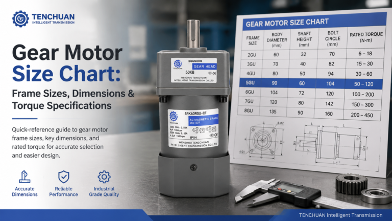
Read a practical gear motor size chart for small AC gear motors. Frame sizes 60-104 mm, dimensions, rated torque and RPM at common ratios, mounting styles.