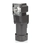

Media 1
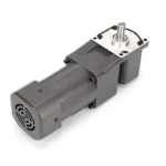
Media 2
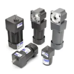
Media 3
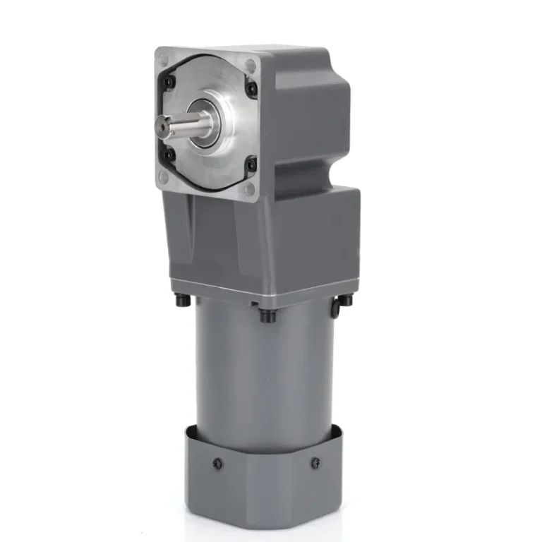
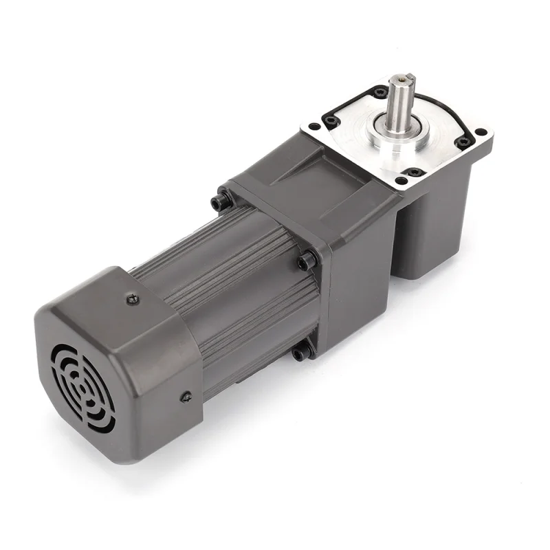
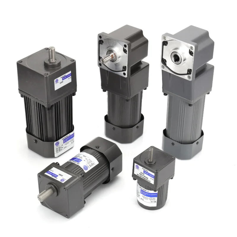
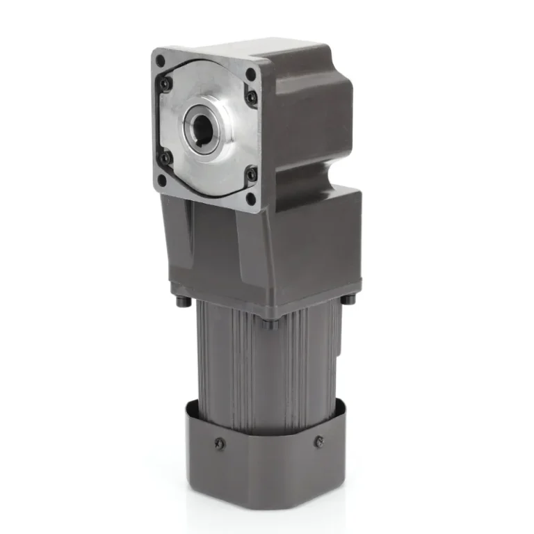
4GN AC Right Angle Gear Reducer Motor 25W
The 4RK series AC gear motor (25–30W) features a compact design and delivers stable performance with reliable torque output. Designed for light to medium-duty applications, it supports both single-phase and three-phase configurations, ensuring efficient operation, consistent speed, and long service life. It is ideal for small automation equipment and precision transmission systems.
- Output Power: 25W / 30W
- Voltage: 110V / 220V (Single-phase & Three-phase options)
- Rated Speed: 1250 – 1550 r/min
- Rated Torque: 154 – 220 mN·m
List of motor characteristics
| Motor Model | Specs | Output Power W | Voltage V | Frequency Hz | Current A | Starting Torque | Rated Torque | Rated Revolution r/min | Capacity/Ve μF/VAC | ||
| JWD Types | mN.m | gf.cm | mN.m | gf.cm | |||||||
| 4RK25GN-C | Reversible 30min | 25 | 1-phase 220V | 50 | 0.24 | 231 | 2310 | 185 | 1850 | 1250 | 2/450 |
| 4RK25A-C | 60 | 0.26 | 192 | 1920 | 154 | 1540 | 1550 | 2/450 | |||
| 4RK25GN-A | Reversible 30min | 25 | 1-phase 110V | 50 | 0.50 | 231 | 2310 | 185 | 1850 | 1250 | 8/250 |
| 4RK25A-A | 60 | 0.56 | 192 | 1920 | 154 | 1540 | 1550 | 8/250 | |||
| 4RK25GN-S | —— | 25 | 3-phase 220V | 50 | 0.24 | 231 | 2310 | 185 | 1850 | 1250 | —— |
| 4RK25A-S | 60 | 0.225 | 192 | 1920 | 154 | 1540 | 1550 | —— | |||
| 4RK30GN-C | Reversible 30min | 30 | 1-phase 220V | 50 | 0.3 | 275 | 2750 | 220 | 2200 | 1250 | 2.5/450 |
| 4RK30A-C | 60 | 0.32 | 231 | 2310 | 185 | 1850 | 1550 | 2.5/450 | |||
| 4RK30GN-A | Reversible 30min | 30 | 1-phase 110V | 50 | 0.60 | 275 | 2750 | 220 | 2200 | 1250 | 10/250 |
| 4RK30A-A | 60 | 0.65 | 231 | 2310 | 185 | 1850 | 1550 | 10/250 | |||
- Parameters in above table refer to motor alone,without any load device.
- Permissible change in rated speed and rated current of the motor is within the range of±5%.
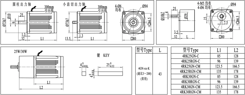
Outline dimension drawing
Allowable load for the gear motor
| Geared-down parameter | Synchronous speed | 500 | 300 | 200 | 150 | 120 | 100 | 75 | 60 | 50 | 40 | 35 | 30 | 25 | 20 | 15 | 12 | 10 | 8 | 7 | 6 | 5 | |
| Ratio | 3 | 5 | 7.5 | 10 | 12.5 | 15 | 20 | 25 | 30 | 36 | 40 | 50 | 60 | 75 | 100 | 120 | 150 | 180 | 200 | 250 | 300 | ||
| Max allowable load | 25W | Kg.cm/N.m | 4.5 0.45 | 7.9 0.79 | 12 1.18 | 15.7 1.55 | 19 1.86 | 23 2.25 | 31.5 3.1 | 35 3.43 | 42 4.12 | 51.1 5.01 | 56.7 5.57 | 62 6.18 | 76.6 7.52 | 80 7.84 | |||||||
| 30W | kg.cm/N.m | 5.7 0.56 | 8.1 0.8 | 14.2 1.39 | 18.9 1.85 | 23.6 2.32 | 28.3 2.78 | 37.8 3.7 | 42.5 4.17 | 51.1 5.01 | 60.2 6.01 | 68.1 6.68 | 65.7 6.5 | 80 7.84 | |||||||||
- The speed is based on the synchronous motor speed reduction ratio as a benchmark calculated by dividing the value of.Actual speed will vary the size of the load changes in less than the values shown in2~15%.
- Hope to the table of the reduction ratio is greater than the further reduction,it would be installed between the motor and the reducer reduction ratiio of 10 the middle of the reducer.
- When the load torque exceeds the maximum allowable load torque gear motor,and a locked rotor situation exists,please slow down box at the junction of the output shaft and load torque limit device installed to ensure the normal operation gearbox.