What Are the Types of Small Reducer Electric Motor?
Published: Author: Lisa
A small reducer electric motor can be classified in several ways: by gear and shaft layout, motor power supply, operating function, output power, and mounting configuration. The most common compact industrial types are parallel-shaft, inline or coaxial, and right-angle gearmotors. Within those mechanical layouts, buyers can choose fixed-speed, reversible, brake-equipped, or speed-controlled versions, as well as single-phase or three-phase AC designs.
Understanding these overlapping categories is important because one motor may belong to several types at once. For example, a unit can be a single-phase, reversible, parallel-shaft motor with a brake and a 60W rating. This guide explains what each classification means and where it fits in conveyors, packaging machines, feeders, turntables, and other compact automation. The Tenchuan Home page provides a broader introduction to Tenchuan’s product range.
What Is a Small Reducer Electric Motor?
A small reducer electric motor combines an electric motor and a reduction gearbox in one compact assembly. The motor supplies high-speed rotation, while the gearhead lowers output speed and multiplies usable torque. Integrating both parts reduces installation space and avoids the alignment work required when a separate motor and reducer are coupled together.
These drives are especially useful when direct motor speed is too high for the machine. A small conveyor may need tens of revolutions per minute at its roller even though the motor operates near 1,500 or 1,800 rpm. A suitable gear ratio converts that speed into slower, stronger output.
Tenchuan’s Small AC Gear Reducer Motors category includes compact models across multiple power levels and ratios. The correct type depends on load, speed, duty cycle, available power, shaft direction, control needs, and installation space.
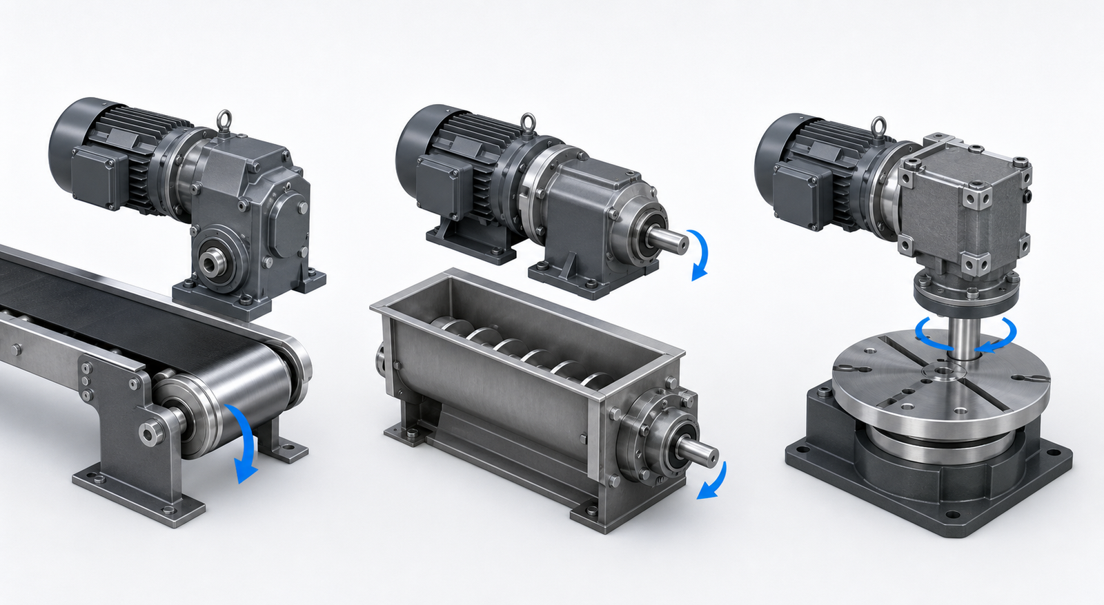
Type 1: Parallel-Shaft Reducer Motors
In a parallel-shaft unit, the motor shaft and output shaft run in parallel, usually with the output offset from the motor centerline. Multiple spur or helical gear stages provide speed reduction inside a compact rectangular gearhead.
This layout is widely used for conveyors, rollers, feeders, and packaging mechanisms because it is straightforward to mount and connect. It can provide good efficiency and a broad range of reduction ratios. The offset shaft may also help place the motor body away from the driven roller or machine frame.
Choose this type when the driven shaft can align parallel to the motor and the machine has enough length for the motor body. Verify the output shaft diameter, keyway, mounting-hole pattern, rotation direction, allowable radial load, and required maintenance clearance.
Type 2: Inline or Coaxial Reducer Motors
An inline or coaxial gearmotor places the motor shaft and output shaft on the same centerline. Depending on the design, the gearhead may use planetary, helical, or other coaxial gear stages. The symmetrical form is useful where the drive must fit directly behind the load.
Inline designs suit dosing equipment, compact feeders, small pumps, and mechanisms where the output must remain centered. Planetary versions can provide high torque density and load sharing in a small diameter, although cost, backlash, ratio range, and efficiency vary by construction.
Do not select an inline motor from appearance alone. Compare rated continuous torque, peak capacity, efficiency, backlash, shaft support, and overall length. A compact diameter may come with a longer body or different mounting requirements.
Type 3: Right-Angle Reducer Motors
A right-angle reducer turns power through 90 degrees. This arrangement is valuable when there is insufficient space behind the driven shaft or when the machine layout naturally requires a perpendicular drive. Common examples include rotary tables, compact conveyors, gates, and transfer mechanisms.
Right-angle gearheads may use worm, bevel, hypoid, or combined gearing. These designs differ in efficiency, noise, backlash, backdrivability, and torque capacity. Never assume that every right-angle motor is self-locking. If a load must be held for safety, use a properly specified brake or external holding device.
Mechanical type
Output relationship
Typical fit
Main checks
Parallel-shaft
Parallel and offset
Conveyors, rollers, feeders
Overhung load, frame length, shaft position
Inline/coaxial
Same centerline
Dosing, pumps, centered mechanisms
Overall length, torque density, backlash
Right-angle
Perpendicular output
Turntables, tight machine layouts
Efficiency, mounting, holding requirement
Types by Motor and Power Supply
Single-Phase AC Gearmotors
Single-phase units are practical where only single-phase mains power is available. They are often used in light machinery and independent equipment. Specify voltage, frequency, and required rotation behavior. A request for “220V” is incomplete without stating whether the supply is single-phase and whether it operates at 50Hz or 60Hz.
Three-Phase AC Gearmotors
Three-phase motors are common in industrial installations and can pair with compatible variable-frequency drives. They generally provide smooth operation and practical direction control, but the motor insulation, frequency range, cooling, and VFD settings must suit the application.
DC and Brushless Gearmotors
Small reducer motors can also use brushed or brushless DC motors. DC versions suit battery-powered or low-voltage equipment and can offer convenient electronic speed control. They require a compatible power supply and controller, so they should not be treated as direct substitutes for an AC gearmotor simply because the output speed and torque appear similar.
Types by Operating Function
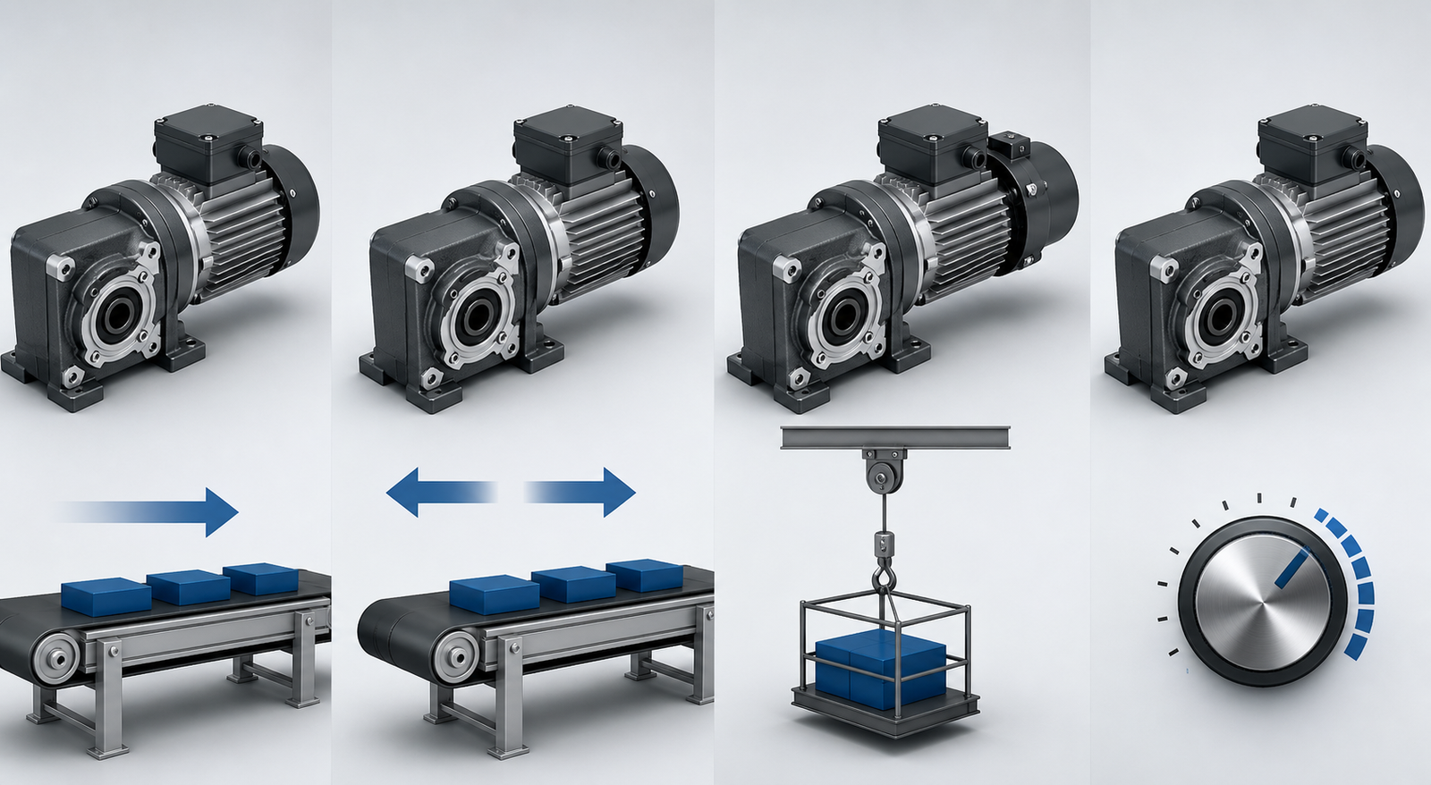
Mechanical layout describes where the shaft points, but functional type describes how the machine must operate. Four common functional groups are fixed-speed, reversible, brake-equipped, and speed-controlled gearmotors.
Fixed-Speed Gearmotors
A fixed-speed motor is the simplest choice for equipment that runs at one steady output speed. The mechanical ratio provides most of the speed reduction. This type works well for continuous conveyors and feeders when the required speed is stable and the load is predictable.
Reversible Gearmotors
Reversible units are designed for applications that change direction, such as gates, positioning mechanisms, and bidirectional conveyors. Specify how often reversal occurs, whether the motor must stop before changing direction, and how much inertia the load carries. Frequent reversing creates additional electrical and mechanical stress.
Brake Gearmotors
A brake-equipped motor can stop or hold the shaft when correctly selected. It is useful for indexing, vertical movement, and equipment that must resist load movement after power is removed. Braking torque, stopping time, duty, release method, and safety requirements must be evaluated separately from running torque.
Speed-Control Gearmotors
A speed-controlled type uses a compatible controller or drive to adjust motor speed. This adds flexibility for production changes, but electronic control cannot correct a fundamentally wrong gear ratio. Prolonged low-speed operation may also reduce motor cooling, so the permitted control range and thermal performance must be confirmed.
Types by Power and Frame Size
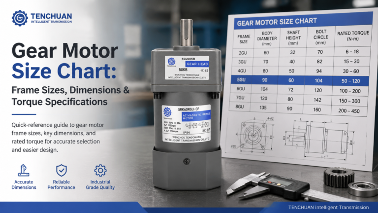
Compact AC reducer motors are also grouped by motor power and matching frame size. Lower-power units suit light loads and intermittent mechanisms, while larger models can support more demanding conveyors or processing equipment. Final capacity still depends on gear ratio and the gearhead’s allowable torque.
The 60W model can be compared for labelers, small rollers, and light conveyors.
The 120W model is relevant to packaging conveyors and transfer mechanisms with higher continuous demand.
The 200W model can be assessed for larger compact conveyors, mixers, and handling equipment.
These power levels are comparison points rather than automatic application matches. Confirm output rpm, continuous and starting torque, ratio, frame, voltage, frequency, phase, duty cycle, and shaft loads for the exact configuration.
How to Choose Between the Types
Define the machine function and required output shaft direction.
Calculate output speed, continuous torque, and starting or peak torque.
Choose parallel, inline, or right-angle geometry from the machine envelope.
Select AC or DC technology based on available power and control needs.
Decide whether fixed speed, reversing, braking, or variable speed is required.
Calculate a preliminary ratio from motor speed and target output speed.
Choose power and gearhead capacity with an appropriate service margin.
Verify shaft dimensions, radial and axial loads, mounting, temperature, and protection.
The Solutions page offers application context that can help narrow the mechanical layout and functional requirements.
Common Classification and Buying Mistakes
Using one label as a full specification: “right-angle” says nothing about power, ratio, voltage, brake, or duty.
Confusing gear type with motor type: an AC motor can be paired with different gearbox architectures.
Choosing by wattage alone: ratio and allowable gear torque determine the actual output.
Assuming a worm drive always holds a load: backdrivability must be verified, and safety-critical loads need a rated holding system.
Ignoring duty cycle: frequent starts, reversals, and continuous running affect heat and life.
Forgetting shaft loads: pulleys and sprockets can overload output bearings even when torque is acceptable.
Choose a Complete Configuration, Not Just a Type Name
The different types of small reducer electric motor overlap. Begin with mechanical layout, then specify motor technology, operating function, power, ratio, mounting, and environmental requirements. A complete specification makes supplier comparisons clearer and reduces the risk of poor fit, overheating, insufficient torque, or unreliable stopping.
Visit About Us to review the supplier background. For application-specific help, send your requirements through Contact Us and request confirmation of the motor type, ratio, torque, voltage, shaft, and mounting configuration.
Frequently Asked Questions
What is the most common small reducer electric motor type?
Parallel-shaft AC gearmotors are common in compact conveyors and general machinery, but the best type depends on shaft direction, space, torque, power supply, and control requirements.
What is the difference between inline and right-angle gearmotors?
An inline gearmotor keeps input and output on the same axis, while a right-angle gearmotor turns the output 90 degrees. The choice is mainly driven by machine layout and performance needs.
When is a reversible motor necessary?
Use a reversible type when the machine must regularly change direction. Confirm reversal frequency, stopping sequence, load inertia, and controller compatibility.
Does a brake motor control speed?
No. A brake stops or holds the shaft; a speed controller changes operating speed. Some systems require both functions.
What information should I send for model selection?
Provide output rpm, continuous and peak torque, duty cycle, voltage, phase, frequency, shaft direction, mounting dimensions, brake and control needs, environment, available space, and expected quantity.
Practical guide to selecting a gear motor for door openers: calculate required torque and output speed, understand self-locking worm gear drives, and match the right AC gear motor to your door type.
Selection guide for gear motors used in hospital beds, infusion pumps, ventilators, lab equipment and other medical devices. Covers noise, precision, IEC 60601-1 safety, IP rating and self-locking requirements, plus a step-by-step selection workflow and application table.
Read a practical gear motor size chart for small AC gear motors. Frame sizes 60-104 mm, dimensions, rated torque and RPM at common ratios, mounting styles.