গিয়ার মোটর কীভাবে তৈরি করা হয়: উৎপাদন প্রক্রিয়া
প্রকাশিত: লেখক: জেলিডাই
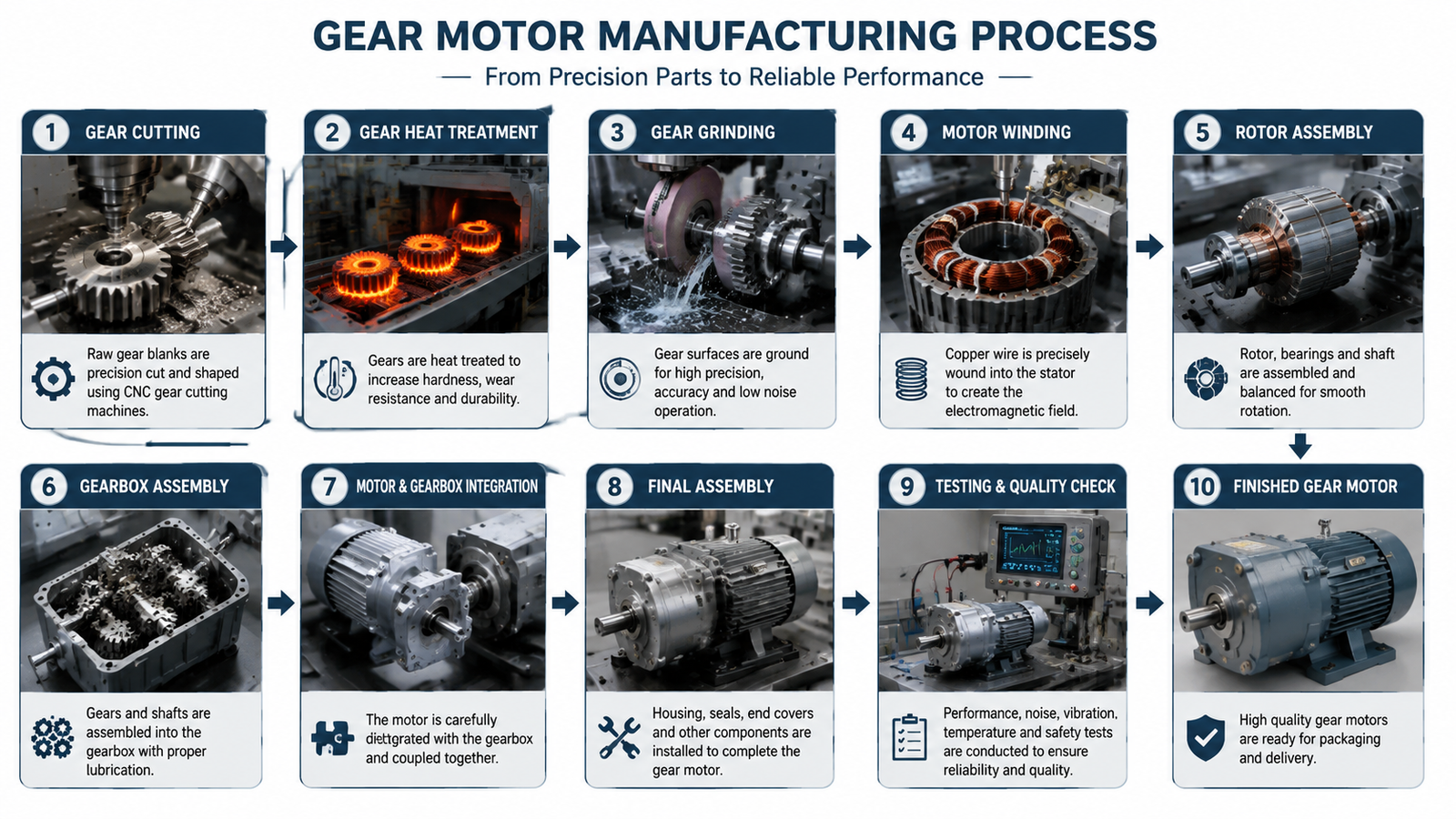
Making a gear motor is not a single step; it is a factory process that builds two separate assemblies and then joins them. A gear motor is an electric motor combined with a reduction gearbox, so production splits naturally into making the motor, making the gears and gearbox, and then assembling and testing the finished unit. In this guide you will see the main steps of that process, from gear cutting and motor winding to final inspection, and learn what separates a dependable small gear motor from one that fails early.
What a Gear Motor Is Made Of
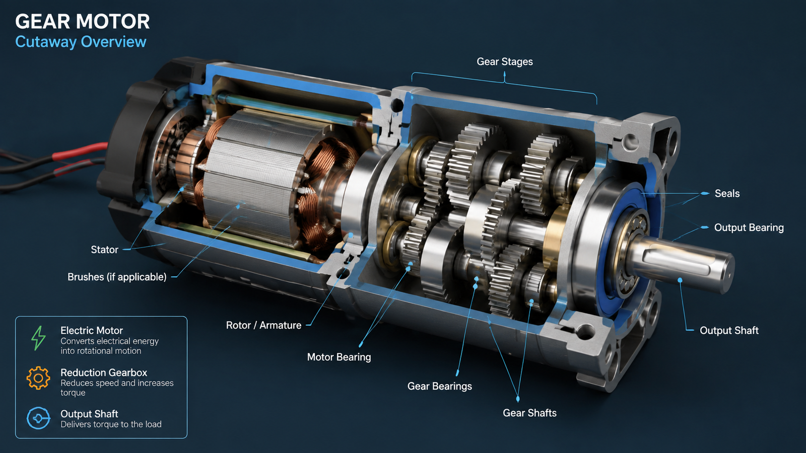
Before the factory can build anything, it starts with the components that define the drive. A gear motor contains two functional halves that are manufactured and then integrated:
The electric motor — a stator with windings, a rotor, and the motor shaft that turns at the rated motor speed.
The reduction gearbox — one or more gear stages, bearings, shafts, seals, lubricant, and a housing that lowers the output speed and multiplies the torque.
The motor produces high-speed, low-torque rotation; the gearbox converts that into lower-speed, higher-torque rotation at the output shaft. If you want the working principle in more detail before looking at production, read গিয়ার রিডাক্সার মোটর কীভাবে কাজ করে.
Step 1: Making the Gears
The gears are the parts that give a gear motor its speed and torque, and they are usually produced first because the gearbox defines the ratio. A factory starts with steel or metal blanks and cuts the gear teeth with precision machines.
Gear teeth are most often cut with a process called hobbing, in which a rotating hob advances across the gear blank to generate the tooth profile in one continuous operation. Depending on the gear type, manufacturers also use shaping, broaching, or grinding. Small spur and helical gears are typical for parallel-shaft reducers, while worm and bevel gears are used when the output shaft must turn at a right angle to the motor.
After cutting, many gears go through heat treatment to harden the tooth surface so it resists wear under load, and precision grinding improves the accuracy of the finished profile. Tighter gear accuracy means quieter running, smoother transmission, and longer service life, which is why CNC machining and precision grinding are central to quality gear production.
Step 2: Making the Motor
On the electrical side, the motor is built around a laminated steel core and copper wire. The stator is wound with coils of wire according to the voltage, phase, and pole count the model requires, then the rotor is fitted so it can spin inside the magnetic field.
For the small AC motors used in most gear reducers, the rotor is typically an induction rotor or a capacitor-run design. The windings and the rotor assembly determine the rated speed, current, and torque of the motor. Professional motor assembly and wiring keep the electrical performance consistent between units, which matters because every gear motor ships as a matched pair: the motor’s speed and torque must line up with the gearbox ratio on the nameplate.
The housing holds every moving part in precise alignment. Housings are usually die-cast or machined, and the bearing seats, bores, and mounting faces are finished to close tolerances. If the bore that supports a bearing is even slightly off, the whole gear train runs out of alignment and wears faster.
The motor shaft, gear shafts, and output shaft are also machined, hardened, and finished at this stage. Each shaft carries bearings and gears, so the journal diameters and keyways are machined accurately to keep the gear mesh stable over the life of the drive.
Step 4: Assembling the Gearbox
With the gears, shafts, bearings, seals, and housing ready, the gearbox is assembled. The shafts are fitted with bearings, the gear stages are positioned so each pair meshes correctly, and seals are installed where the shafts pass through the housing so lubricant stays in and contamination stays out.
The gearbox is then filled with the correct lubricant for the gear type and ratio. Worm stages, for example, need a different lubricant and viscosity than spur or helical stages because the sliding contact creates more friction and heat. Assembly control directly affects noise, vibration, and efficiency, so the order and torque of every fastening step matters.
Step 5: Joining Motor and Gearbox
The final mechanical step is joining the motor and the gearbox into one integrated unit. In an integrated gear motor, the motor shaft carries a pinion that meshes directly with the first gear stage inside the gearbox, so no separate coupling is needed. The housing bolts hold the two halves together, and the pinion-to-gear engagement must be set accurately to avoid backlash or binding.
Because the reduction ratio comes from the number of teeth in each meshing pair, the ratio was effectively fixed when the gears were designed and cut. If you need to understand how that ratio is calculated for a specific output speed, the gear ratio calculation guide walks through the math.
Step 6: Testing and Quality Control
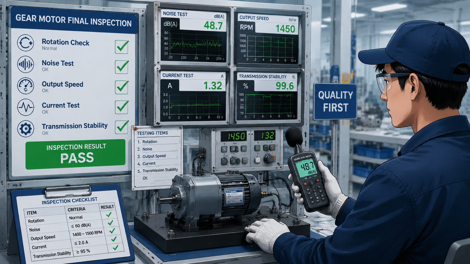
No gear motor leaves a serious factory without a run test. Each unit is connected to power and checked for smooth rotation, acceptable noise, correct output speed, and stable transmission. Final inspection typically covers:
Rotation and startup — the shaft turns freely and the motor starts reliably at the rated voltage.
Noise and vibration — running sound stays within the design range, which is a fast signal of gear accuracy and assembly quality.
Output speed and current — the measured output matches the nameplate speed within tolerance and the current draw is normal.
Load and transmission stability — the gearbox delivers steady torque without skipping, binding, or overheating.
These checks are the reason two gear motors with the same power rating can perform very differently: the testing and the tolerances behind it determine how long the unit runs quietly under load.
What Manufacturing Quality Means for Buyers
When you buy a gear motor, you are buying the outcome of every step above. Accurate gears and housings mean lower noise and longer life; consistent winding and assembly mean the motor performs to its nameplate; and real testing means the unit you receive matches the one that was designed.
This is why it pays to evaluate the manufacturer as well as the model number. Look for a producer that does the machining, assembly, and inspection in-house rather than only buying and branding parts. Tenchuan, for example, manufactures small AC gear reducer motors from 15W to 300W and states its process openly: gear reducer motor manufacturing uses CNC machining, gear grinding, professional motor assembly, and a final inspection of rotation, noise, output speed, and transmission stability on every unit.
Once you know the process is dependable, the rest is selection: required output speed, torque, ratio, duty cycle, voltage, and mounting. The guide on how to choose a small gear reducer motor takes you through those steps, or you can compare the small AC gear reducer motors directly.
প্রায়শই জিজ্ঞাসিত প্রশ্নাবলী
Can you make a gear motor at home?
You can assemble a simple geared drive by attaching an off-the-shelf gearbox to a hobby motor, and many DIY projects do exactly that. Producing a precision industrial gear motor, however, requires gear cutting, heat treatment, matched windings, and testing that a machine shop or factory performs, so commercial units are manufactured rather than hand-built.
What materials are gear motor gears made of?
Gears in small gear motors are usually made of hardened steel or a sintered metal for the tooth mesh, sometimes with plastic gears in very light-duty models. The choice depends on the torque, duty, noise, and cost targets of the application.
How are gear teeth cut in a factory?
The most common method is hobbing, where a rotating hob cuts the teeth progressively into the blank. Shaping, broaching, and precision grinding are also used, with grinding added after heat treatment to refine accuracy and reduce noise.
What is the difference between a gear motor and a reduction gearbox?
A gearbox is the reduction assembly on its own. A gear motor is the complete integrated unit with the electric motor attached. Most small industrial drives are sold as integrated gear motors so the pinion engagement and alignment are set at the factory.
How is the output speed of a gear motor set during manufacturing?
Output speed is set by the motor’s rated speed divided by the gearbox reduction ratio, which is determined by the number of teeth in each gear stage. Because the ratio is built into the gears, the factory cuts the correct tooth combinations for each requested output speed.
From Raw Parts to a Finished Gear Motor
Making a gear motor means producing the motor and the gearbox separately, then joining and testing them as one drive. The gears are cut, hardened, and ground; the motor is wound and assembled; the housing and shafts are machined; the gearbox is assembled and lubricated; and every unit passes a run test before it ships. That process is what turns raw materials into a drive you can install and trust.
If you are sourcing a gear motor for a machine, review the product range or contact the Tenchuan team with your required speed, torque, voltage, and mounting details for a recommendation built on a verified manufacturing process.
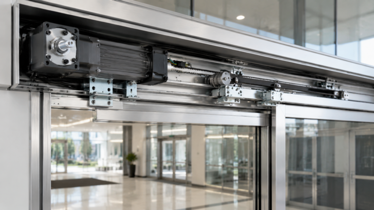
Practical guide to selecting a gear motor for door openers: calculate required torque and output speed, understand self-locking worm gear drives, and match the right AC gear motor to your door type.
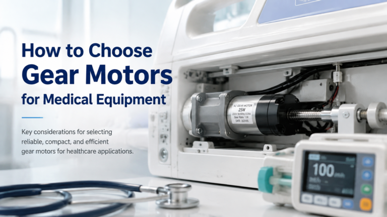
Selection guide for gear motors used in hospital beds, infusion pumps, ventilators, lab equipment and other medical devices. Covers noise, precision, IEC 60601-1 safety, IP rating and self-locking requirements, plus a step-by-step selection workflow and application table.
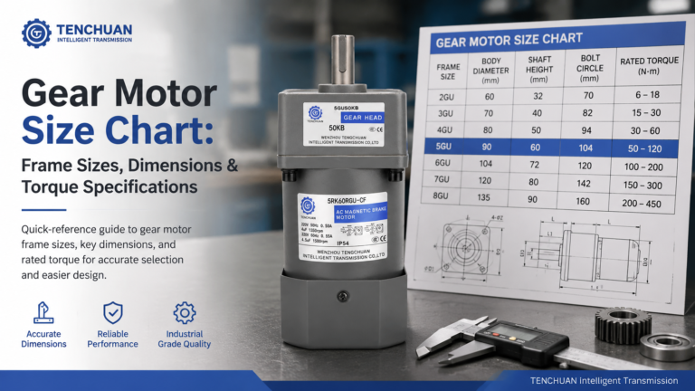
Read a practical gear motor size chart for small AC gear motors. Frame sizes 60-104 mm, dimensions, rated torque and RPM at common ratios, mounting styles.