Gear Motors for Agitators and Mixers: Low-Speed, High-Torque Selection
প্রকাশিত: লেখক: লিসা
Agitator drives fail in a specific and predictable way: the motor trips on the first start of the morning, or the gearbox runs hot within a few weeks, or the mix never reaches the consistency the process needs no matter how long it runs. In almost every case the drive was selected on the tank volume or on the kilowatt rating of a similar mixer, and the two numbers that actually decide the outcome — starting torque and thrust load — were never calculated.
This guide works through the calculation for small and medium tanks: how to get from impeller geometry and fluid to a shaft torque, where viscosity changes the service factor, which loads a gear motor is genuinely not designed to carry, and how to tell when a medium-frame AC gear reducer motor is the right answer and when it is not.
Start with the impeller, not the tank
The power a mixer absorbs is not set by the volume of liquid in the tank. It is set by the impeller, the speed and the fluid:
P (W) = Np × ρ × N³ × D⁵

  Np = impeller power number (dimensionless, from the impeller supplier)
  ρ  = fluid density, kg/m³
  N  = impeller speed in revolutions per second (r/min ÷ 60)
  D  = impeller diameter in metres
Two exponents in that formula do most of the damage. Power scales with the cube of speed, so a 20% speed increase needs 73% more power. Power scales with the fifth power of impeller diameter, so a 20% larger impeller needs 2.5 times the power. Process trials that “just speed it up a little” or “just fit a bigger blade” move the drive requirement by a factor, not a percentage, and that is why the drive should be finalised after the impeller is fixed rather than before.
Impeller
Typical Np
Typical speed
Character
Hydrofoil (axial flow)
0.3 – 0.5
80 – 150 r/min
High bulk flow, low shear, efficient
45° pitched-blade turbine
1.2 – 1.4
60 – 120 r/min
General purpose blending and solids suspension
Rushton disc turbine
4.5 – 5.5
50 – 100 r/min
High shear, gas dispersion, much higher power draw
Anchor or helical ribbon
Geometry dependent
10 – 40 r/min
Very high torque at very low speed, close-clearance duty
Note what the table implies about gear motors. A Rushton turbine at 90 r/min needs roughly four times the power of a pitched-blade turbine of the same diameter at the same speed, and an anchor at 20 r/min can need more torque than a turbine four times its power. Torque, not power, is what the gearbox has to transmit — and the two are inversely related through speed.
Convert impeller power into shaft torque
The gear motor is selected on output torque, so the power figure has to be converted at the actual mixing speed:
T (N·m) = 9550 × P (kW) ÷ n (r/min)
Run that for a range of powers and speeds and the shape of the problem becomes obvious.
Motor class
At 30 r/min
At 60 r/min
At 90 r/min
At 120 r/min
400 W
114 N·m
57 N·m
38 N·m
29 N·m
৭৫০ ওয়াট
215 N·m
107 N·m
72 N·m
54 N·m
1500 W
429 N·m
215 N·m
143 N·m
107 N·m
2200 W
630 N·m
315 N·m
210 N·m
158 N·m
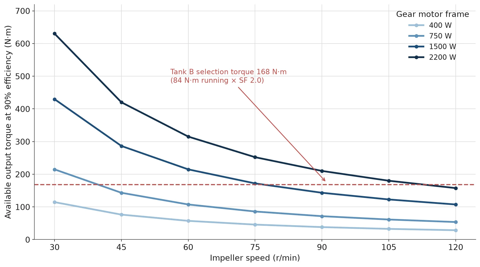
These are theoretical output torques at 90% gearbox efficiency, before any service factor. They are the ceiling, not the target: a drive chosen exactly at these numbers has no margin for a viscous start, and the gearbox’s own rated output may be lower than the calculation at high ratios — the same ceiling effect described in the five-step reducer sizing walkthrough. Always compare against the published rating at the exact ratio.
Viscosity sets the service factor, and it is not the average
This is where agitator selection diverges from conveyor selection. A conveyor’s load is fixed by machine geometry; an agitator’s load is defined by the fluid, and the fluid changes.
Process viscosity
Typical products
সেবা গুণক
Why
Below 100 cP
Water, solvents, thin blends
1.5
Start torque close to running torque
100 – 10,000 cP
Paints, slurries, syrups, pastes
2.0
Yield stress and settling raise breakaway torque well above running torque
Above 10,000 cP
Heavy sludge, filled polymers, dough
2.5 – 3.0
Laminar flow, high apparent viscosity at start
Use the worst credible viscosity of the recipe, not the viscosity on the product data sheet. Many processes start thin and thicken — a reaction, a hydration step, a temperature drop overnight. A drive sized on the thin end starts every batch at several times its design torque, and the damage accumulates in the gear teeth as fatigue rather than showing up as an immediate failure.
The starting case is worse than the service factor suggests. A turbine impeller starting in a settled 5,000 cP slurry can demand four to six times its steady running torque before the fluid yields. No compact AC gear motor will start a fully settled viscous batch from cold at that multiple. The process has to help: start the impeller before solids settle, use a VFD with a ramped start, or fit a variable-speed start that brings the impeller up slowly as the fluid yields. Sizing the motor large enough to break out a settled batch by brute torque is usually the most expensive possible answer.
The load a gear motor is not designed to carry
Here is the point that separates an honest agitator specification from a catalogue match. A top-entry agitator imposes two loads on the drive that a gear motor’s output bearing was never sized for.
Thrust. The impeller produces axial force — up or down depending on flow direction — and the shaft’s own weight adds to it. On a 3000 L tank with a 0.7 m impeller, that can be several hundred newtons, and on a long shaft with a bottom steady bearing it can be more.
অতিরিক্ত ঝুলন্ত भार. Any side force at the impeller, plus shaft run-out and any imbalance, becomes a bending moment at the output bearing. Overhung load limits are published per shaft position (typically at 10 mm and 20 mm from the shaft end) and they are far lower than the torque rating suggests.
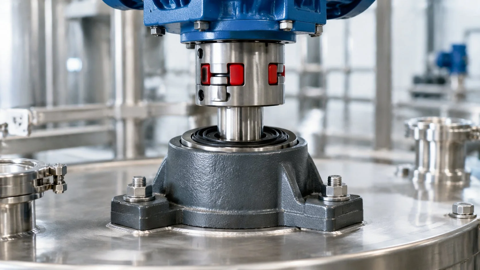
The practical consequence: on anything but a very small tank, the agitator shaft should not hang directly on the gear motor’s output shaft. Use a separate bearing housing or a pillow block that takes the thrust and the bending moment, and connect the gear motor to the shaft with a flexible coupling. The gear motor then transmits torque only — which is what it is designed for. Skipping this step is the single most common reason a correctly-sized agitator drive fails its output bearing within a year.
For side-entry agitators the same logic applies with the loads rotated: the shaft cantilever and seal loads go into a bearing housing, and a right-angle gear motor is used where the layout needs the motor to sit at 90° to the shaft.
Vertical or horizontal mounting
Top-entry agitators almost always use the vertical configuration: motor above, output shaft down, flange mounting to the tank top or to the bearing housing. Three details matter at order.
Oil and seal orientation. A vertical drive has different lubricant distribution from a horizontal one, and the seal arrangement is different. A horizontal unit rotated on site to vertical can leak or starve a bearing. Specify the mounting position at order.
Condensation. Tanks are often washed down and the drive sits in a humid headspace. Specify the enclosure and, where relevant, a drain hole orientation so condensate escapes rather than collecting in the terminal box.
Access. The coupling and the bearing housing need to be serviceable without removing the tank lid. That is a layout decision, but it is made when the drive is chosen.
Worked example: two tanks, same speed, different frames
Tank A — 1,000 L blend. 45° pitched-blade turbine, Np 1.27, D 0.55 m, 90 r/min, ρ 1,000 kg/m³, viscosity about 200 cP.
N = 90 ÷ 60 = 1.5 rev/s
P = 1.27 × 1,000 × 1.5³ × 0.55⁵ ≈ 0.22 kW at the impeller
Torque = 9550 × 0.216 ÷ 90 ≈ 22.9 N·m
Service factor 2.0 → 45.8 N·m selection torque
A 750 W drive at 90 r/min offers about 72 N·m, which covers it with margin. A 400 W unit at 38 N·m does not.
Tank B — 3,000 L slurry. Same impeller type, Np 1.27, D 0.7 m, 90 r/min, ρ 1,100 kg/m³, viscosity about 800 cP.
P = 1.27 × 1,100 × 1.5³ × 0.7⁵ ≈ 0.79 kW at the impeller
Torque = 9550 × 0.792 ÷ 90 ≈ 84 N·m
Service factor 2.0 → 168 N·m selection torque
A 1500 W drive at 90 r/min offers about 143 N·m — not enough at this service factor
দ্য 2200 W frame at the same speed offers about 210 N·m, which covers 168 N·m
Read the pair together. Both tanks turn at the same speed; Tank A needs 750 W and Tank B needs 2200 W. The difference is impeller diameter and density, not tank size as such — 3× the volume required 3× the power because the impeller had to grow with the tank. A selection that started from “litres of tank” would have got neither answer reliably right.
Tank B also illustrates the starting problem. At four to six times the running torque, a settled 800 cP batch would demand 340–500 N·m at start. The 2200 W frame offers 210 N·m continuously and appreciably more briefly, but not that much. The process answer is a VFD ramp and a start before settling, not a bigger gearbox.
Mistakes that repeat in agitator drive selection
Mistake
What happens
Correction
Selecting from tank volume or a similar mixer’s kilowatts
Drive is undersized or pointlessly oversized
Calculate P from Np, ρ, N and D, then convert to torque
Using average viscosity for the service factor
Gearbox fatigue failure within a season
Use the worst credible viscosity in the recipe
Hanging the agitator shaft on the gear motor output
Output bearing fails; seal leaks
Separate bearing housing plus flexible coupling
Expecting the gear motor to break out a settled batch
Motor stalls or trips on start every morning
VFD ramp, or keep solids in suspension, or start unloaded
Rotating a horizontal unit to vertical on site
Oil starvation, seal leak
Order the correct mounting configuration
Ignoring the allowable load ceiling at high ratio
Gear damage despite a “correct” torque calculation
Read the allowable load at the exact ratio
Viscosity also behaves differently in a pump and in a tank: a pump sees the fluid once at a fixed shear rate, an agitator sees it at varying shear through the batch. The viscosity correction logic for pumps is set out in the pump drive guide, and it is a useful starting point but not a substitute for the impeller calculation above. The service factor and duty framework that sits underneath both is in the gearbox service factor guide.
When a medium-frame gear motor is the wrong answer
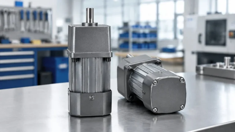
Be clear about the boundary. The medium AC gear reducer range tops out at 3.7 kW, with a 32 mm output shaft at 1500 W and larger shafts above. That covers small process tanks, pilot plants, IBC and tote mixing, dosing and neutralisation tanks, and food or chemical batches up to a few thousand litres.
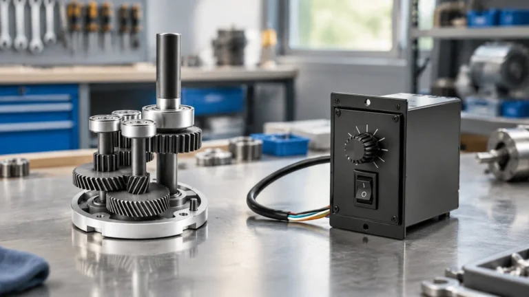
Beyond that the correct drive is an industrial agitator gearbox: helical or helical-bevel, hollow-shaft or flange-mounted, with an integral thrust bearing rated for the shaft load and a dry-well seal arrangement. Those units are designed from the start around the axial and radial loads a large impeller produces. Trying to reach the same duty by fitting a bigger AC gear motor and a longer shaft is how projects end up with a leaking seal and a failed bearing in the first year.
উপসংহার
Agitator drive selection is four numbers and one check: impeller power from Np, ρ, N and D; torque at the mixing speed; a service factor that follows the worst viscosity in the recipe; a starting margin for settled product; and then a check that the thrust and overhung loads are going into a bearing housing rather than into the gear motor.
Send us the tank size, impeller type and diameter, mixing speed, fluid density and the worst viscosity, and we will calculate the torque and tell you which frame covers it — including when the honest answer is that the duty belongs to an industrial agitator gearbox rather than a compact AC drive.
প্রায়শই জিজ্ঞাসিত প্রশ্নাবলী
How do I choose a gear motor for an agitator?
Calculate the impeller power from Np × ρ × N³ × D⁵, convert it to torque at the mixing speed with T = 9550 × P ÷ n, multiply by a service factor based on the worst viscosity in the recipe, then select a frame whose published output torque at that ratio exceeds the result.
Why does tank volume not determine the motor size?
Because power depends on the impeller and the speed, not the volume. A large tank with a small slow impeller can draw less power than a small tank with a large fast one. Volume affects the drive only through the impeller size and speed the process requires.
Can a gear motor start a settled slurry?
Rarely. Breakaway torque in a settled viscous batch can be four to six times the running torque. Use a VFD with a ramped start, avoid letting solids settle, or start the impeller before the tank is fully charged.
Does the gear motor carry the agitator shaft weight?
On very small tanks only. Above that, fit a separate bearing housing or pillow block to take the thrust and bending loads, and connect the gear motor through a flexible coupling so it transmits torque only.
What service factor should an agitator drive use?
About 1.5 for water-like fluids below 100 cP, 2.0 for 100–10,000 cP, and 2.5–3.0 above 10,000 cP. Base it on the worst viscosity the recipe can reach, not the typical value.
Can I use a right-angle gear motor for a side-entry agitator?
Yes, where the layout needs the motor at 90° to the shaft, provided the shaft loads still go into a bearing housing and the mounting position is specified at order so the lubricant and seal arrangement match.
The 30-minute rating on a reversible gear motor is a thermal statement, not a timer. What it limits, how to read your duty cycle against it, and how to run longer without buying the wrong motor.
How a speed controller actually slows an AC gear motor, why torque falls to about a third at the bottom of the range, how to wire it, and when a VFD or a different gear ratio is the better answer.
Five steps from a machine to a torque number: converting load to force, force to shaft torque, correcting for gearbox efficiency, applying a service factor, and checking the result against the allowable load table.