AC Gear Motor Torque Calculation: From Load to Required Output Torque
Ngày đăng: Tác giả: Lisa
Nearly every gear motor that fails early was selected on power. The buyer reads “90 W”, matches it to the 90 W motor on the old machine, and orders. But the gearbox does not care about watts. It cares about the torque on its output shaft, and two 90 W drives at different ratios can differ by a factor of thirty in what they will carry.
This guide is the arithmetic of getting from a machine to a torque number, and then from that number to a model in the catalogue. It does not re-derive the ratio — that is a separate calculation covered in Cách tính tỷ số truyền. Here the ratio is an input, and torque is the output.
The one formula, and where it is not enough
Power, speed and torque are locked together:
T (N·m) = 9550 × P (kW) ÷ n (r/min)

For a gear motor the useful form is the output shaft:
T_out = 9550 × P × η ÷ n_out

  P    = motor power in kW
  η    = gearbox efficiency (≈0.90 for a 2-stage helical reduction)
  n_out = motor speed ÷ gear ratio
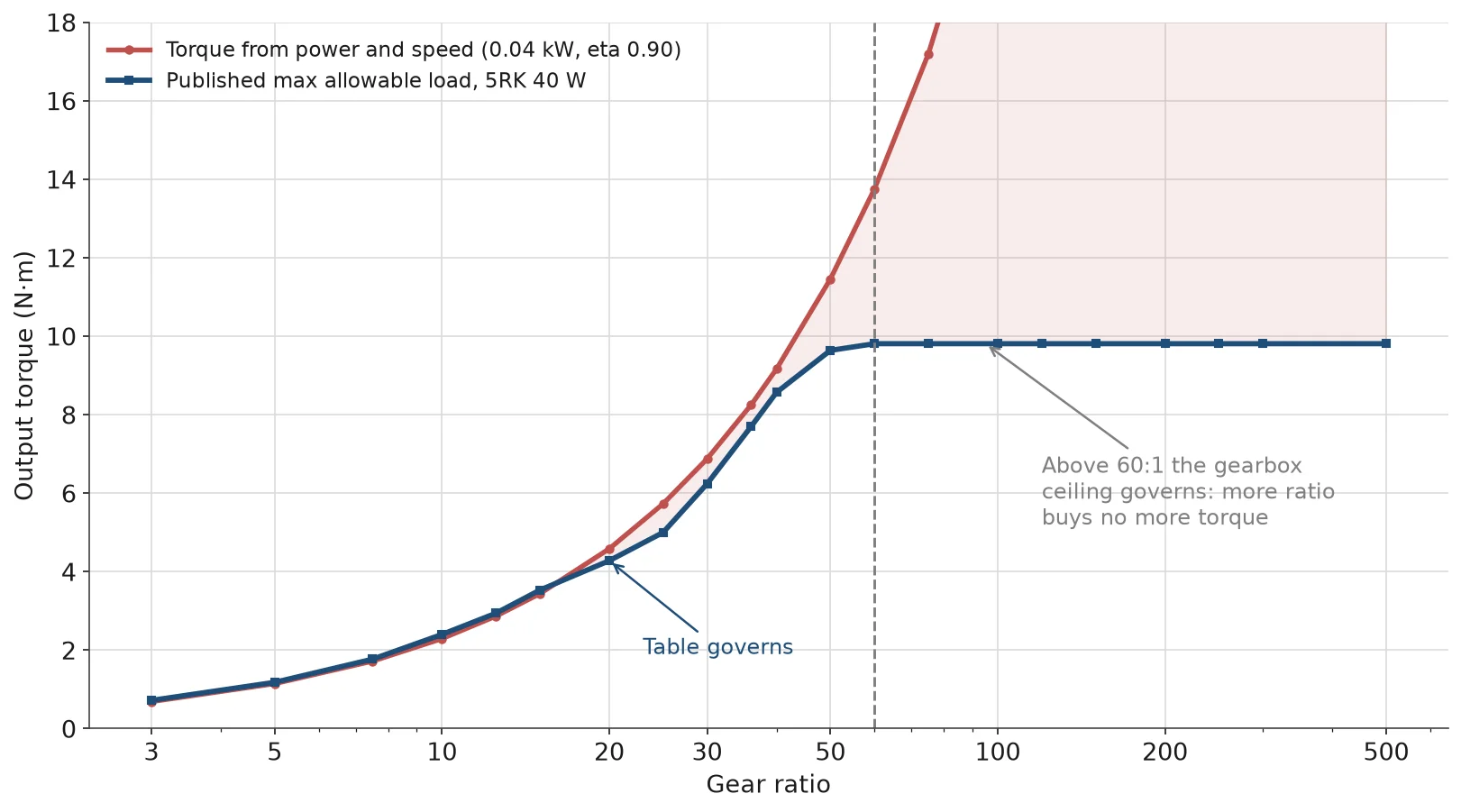
This gives you the torque the drive can produce. It does not tell you the torque the gearbox is allowed to transmit, and those are two different limits. On a compact AC gear motor the allowable load is published as a table against each ratio, and at high ratios the table stops rising while the formula keeps going. That gap is where most over-specified and most under-protected drives come from, and it is the subject of step 5 below.
Step 1: Turn the machine into a force in newtons
Whatever the mechanism, the first move is always the same: express the resistance as a single force at the point where the drive acts.
Machine
Force components
Note
Horizontal conveyor or roller bed
F = μ × m × 9.81 + m × a
μ for a loaded belt on a steel bed typically 0.05–0.15; use the higher figure for a poorly maintained belt
Băng tải nghiêng
F = μ × m × 9.81 × cos θ + m × 9.81 × sin θ + m × a
The gravity term dominates above roughly 15°; do not use cos θ ≈ 1 there
Vertical lift or hoist
F = m × 9.81 + m × a
Also needs a brake or a mechanical holding device; the gearbox is not a safety device
Chain or belt with a hanging load
F = m × 9.81 (each side adds separately)
Include chain weight on long spans
Screw or jack
F = m × 9.81 + friction; torque = F × pitch ÷ (2π × η_screw)
Screw efficiency is poor at low lead angle, often 0.3–0.5
Two habits make this step reliable. Use the total moving mass, including belts, chains, fixtures and the product — buyers routinely use the product weight alone and end up 30% light. And treat acceleration as a real force rather than a service factor. Accelerating 80 kg at 0.3 m/s² needs 24 N, which on a 50 mm radius pulley is 1.2 N·m of extra torque that never appears in a steady-state calculation.
Step 2: Turn the force into shaft torque
Torque at the driven shaft is force times radius:
T (N·m) = F (N) × r (m)
The radius must be the effective radius, measured to the working surface, not the bare drum. A 100 mm drum with 4 mm of lagging has an effective diameter of 108 mm, which is 8% more radius and 8% more torque for the same force. On a machine with a tight process window that is the difference between running in tolerance and not.
For a rotating load driven directly — a turntable, a mixer impeller, a roller — skip the force route and use inertia and angular acceleration instead:
For a solid disc of mass m and radius r, J = 0.5 × m × r². A 40 kg turntable of 0.4 m radius has J ≈ 3.2 kg·m²; accelerating it to 15 r/min in 1 s needs α ≈ 1.57 rad/s² and therefore about 5.0 N·m of acceleration torque, on top of whatever friction the bearing adds. That number is frequently larger than the running torque, and it is invisible if you only size on steady state.
Step 3: Account for the gearbox honestly — divide, do not multiply
The tempting shortcut is to take the motor’s rated torque and multiply by the ratio. That overstates the output, because every gear stage loses power to mesh friction and bearing drag.
T_out(available) = T_motor × i × η

Reverse direction, which is what selection usually needs:
T_motor(required) = T_load(required at output) ÷ (i × η)
With η = 0.90, a 5:1 reduction returns 4.5 times the motor torque, not 5. The 10% is not a rounding detail: on a 15 N·m requirement it is 1.5 N·m, which is often the difference between the ratio you chose and the next one up. The same applies when comparing two frames that share a load ceiling — a 90 W unit và một 120 W unit on the same 90 mm frame both stop at 19.6 N·m allowable load, so above roughly 50:1 the extra 30 W buys efficiency margin rather than usable torque.
Efficiency is not a constant. It falls as the number of stages rises, so a 100:1 unit is less efficient than a 10:1 unit of the same family, and it falls again at very light load where the mesh friction becomes a larger fraction of the transmitted power.
Step 4: Add the service factor that matches the duty
Running torque is a snapshot. Machines see start-up friction, occasional jams, unbalanced product, ambient heat and duty cycles that the drawing does not show. The service factor covers that gap.
Duty character
Hệ số dịch vụ
Các loại máy thông dụng
Smooth, uniform, well characterised
1.0 – 1.25
Continuous conveyor, fan, light roller
Moderate shock or frequent starting
1.25 – 1.5
Packaging indexer, door operator, labelling station
Heavy shock, high inertia, reversing
1.5 – 2.0
Mixer start in settled product, gate with wind load, punch feed
Viscous fluid, settled solids, cold start
2.0 – 3.0
Slurry agitator, paste transfer, unheated grease line
Selection torque is running torque multiplied by the service factor, and the model must satisfy that number, not the running torque. A large service factor is not a substitute for a bad load estimate — it buys cost and size you may not need while masking an error you will still have.
Step 5: Match the number to the allowable load table
This is the step that separates a correct selection from a spreadsheet that looks correct. Compact AC gear motors publish an allowable load table per ratio, and it is not a straight line. Here is the published table for the 40 W 5RK series unit on the 90 mm frame.
Tỷ lệ
Tốc độ đầu ra ở tần số 50 Hz (vòng/phút)
Max allowable load (N·m)
3:1
500
0.72
5:1
300
1.18
10:1
150
2.40
15:1
100
3.53
20:1
75
4.28
30:1
50
6.24
40:1
37.5
8.57
50:1
30
9.64
60:1
25
9.81 (ceiling)
100:1 – 500:1
15 down to 3
9.81 (ceiling)
Two things fall out of that table, and neither is obvious from a power figure.
The table is a ceiling, not a promise. At 60:1 and above the allowable load is 9.81 N·m regardless of ratio. Going from 60:1 to 300:1 does not let you hang five times more load on the shaft — it only makes the shaft turn five times slower. The ratio multiplies the motor’s torque up to the point where the gearbox’s own mechanical strength, not the motor, becomes the limit.
The correct check is the lower of two numbers. At each ratio, compare the torque you calculated in step 3 with the table value and take the smaller. A 40 W drive at 10:1 produces roughly 0.28 × 10 × 0.9 ≈ 2.5 N·m by formula and is allowed 2.40 N·m by the table, so the table governs. At 3:1 the formula gives about 0.76 N·m and the table allows 0.72 — again the table. The formula tells you what the motor can push; the table tells you what the gearbox will survive.
The four torques that are not the same number
Specification sheets use “torque” for four different quantities, and mixing them is where selections go wrong.
Quantity
Meaning
Khi nó điều hành
Rated (running) torque
Continuous torque at rated speed and temperature
Steady conveying, continuous mixing
Mô-men xoắn khởi động
Torque available at standstill; roughly 1.2–1.8× rated on a single-phase gear motor, about 2–2.5× on three-phase
Starting a loaded conveyor or a settled fluid
Peak / acceleration torque
Short-duration torque during acceleration or a jam
High-inertia starts, indexing moves
Holding torque
Torque needed to keep a load stationary with no power
Vertical lifts, gates — and it requires a brake, not a gearbox
Starting torque is the one buyers most often ignore. A drive that satisfies the running torque calculation can still fail to start a machine whose static friction is twice its running friction — a belt that has sat loaded overnight, a screw jack under compression, a mixer in settled solids. If the machine starts loaded, size on starting torque, not running torque.
Two short worked examples
A chain-driven roller bed. Moving mass 120 kg, friction coefficient 0.08, target speed 0.25 m/s, drive sprocket 0.06 m radius, acceleration 0.2 m/s² over 1.25 s.
Friction force: 0.08 × 120 × 9.81 ≈ 94 N
Acceleration force: 120 × 0.2 = 24 N
Total force ≈ 118 N
Torque at the sprocket: 118 × 0.06 ≈ 7.1 N·m
Service factor 1.4 → selection torque ≈ 9.9 N·m
At 0.25 m/s with a 0.06 m sprocket the shaft must turn at about 40 r/min. A 90 W motor at 1400 r/min needs roughly 35:1, and the allowable load at that ratio on a 90 mm frame comfortably exceeds 9.9 N·m — so a 90 W unit is enough, and a 120 W unit buys margin rather than capability.
A screw jack lifting 60 kg. Load 60 kg, screw pitch 4 mm, screw efficiency 0.4, no acceleration allowance.
Force: 60 × 9.81 ≈ 589 N
Screw torque: 589 × 0.004 ÷ (2π × 0.4) ≈ 0.94 N·m
Service factor 1.5 → 1.4 N·m
That looks small, but the jack must also hold when stopped, and a compact AC gear motor will not do that. The selection needs an electromagnetic brake or a self-locking screw thread confirmed by the screw supplier — the gearbox alone is not a holding device, a point worth stating plainly before a load is suspended over a walkway.
Mistakes that show up in real selections
Sai lầm
Kết quả
Sửa lỗi
Sizing on motor watts against a similar-looking machine
Wrong ratio, wrong frame, stalls under load
Calculate the load torque; power follows from torque and speed
Multiplying motor torque by the ratio and ignoring η
Selection is 10% optimistic
Divide by (i × η) when working back to the motor
Assuming allowable load scales with ratio
Overload on the gearbox above the ceiling ratio
Read the allowable load table at the exact ratio
Using the bare drum radius
Underestimates torque by the lagging allowance
Measure to the working surface
Ignoring acceleration torque
Drive trips or stalls on start, runs fine after
Add J × α for rotating loads and m × a for linear ones
Using a gearbox as a holding brake
Tải bị lệch hoặc rơi khi mất điện
Specify a brake motor or a mechanical holding device
The full ordered workflow, including ratio selection and the mechanical checks that torque does not cover, is set out in the five-step reducer sizing walkthrough. If the machine is a conveyor specifically, the material handling drive guide applies the same arithmetic to belt speed and pulley diameter. Where the layout needs the output shaft at 90° to the motor, the same torque arithmetic applies but the allowable load table belongs to a different family — the right-angle 6GU units carry a different ceiling at each ratio and cannot be read off the parallel-shaft table. And if the required torque is already known and only the model is in question, the frame and torque chart lets you shortlist by frame before checking the ratio table.
Kết luận
Torque calculation is five steps in a fixed order: reduce the machine to a force, convert to shaft torque at the effective radius, divide by efficiency when working back to the motor, multiply by a service factor that matches the duty, and then check the result against the allowable load table at the exact ratio you intend to order. The formula gives you a capability; the table gives you a permission. A correct selection satisfies both.
If you have the load, the speed and the duty, send them over — we will return the ratio, the frame and the allowable load at that ratio, and tell you if the answer is a bigger motor or a different mechanism.
Câu hỏi thường gặp
Should I size a gear motor on torque or on power?
On torque. Power is torque multiplied by speed, so it only becomes meaningful once the output speed is fixed. Sizing on power alone lets a high-speed, low-torque drive look equivalent to a low-speed, high-torque one when it is not.
What is the difference between rated torque and allowable load?
Rated torque is what the motor can produce continuously at its rated speed. Allowable load is the maximum torque the gearbox output shaft may transmit at a given ratio. The selection must satisfy the lower of the two.
Why does the allowable load stop increasing above a certain ratio?
Because the limit stops being the motor and becomes the gearbox — gear tooth strength, bearing capacity and shaft stiffness. Adding ratio beyond that point reduces speed without adding usable torque.
What efficiency should I use for a compact gear motor?
About 0.85–0.92 for a two-stage helical reduction, falling as stages are added. Use 0.90 as a working figure and ask the supplier for the value at your specific ratio if the selection is close.
How much service factor do I need?
1.0–1.25 for smooth continuous loads, 1.25–1.5 for frequent starting or moderate shock, and 1.5–2.0 or more for high inertia, reversing or viscous starting. Use the larger figure when the load is poorly characterised.
Does a gear motor hold a load when the power is off?
Not reliably. Some gear geometries resist back-driving, but that is a geometry tendency, not a rated holding function. Use a brake motor or a mechanical holding device wherever the load must stay put without power.
Agitator drives fail on starting torque and thrust load, not on kilowatts. How to calculate impeller power, convert it to shaft torque, and where a gear motor stops being the right drive.
The 30-minute rating on a reversible gear motor is a thermal statement, not a timer. What it limits, how to read your duty cycle against it, and how to run longer without buying the wrong motor.
How a speed controller actually slows an AC gear motor, why torque falls to about a third at the bottom of the range, how to wire it, and when a VFD or a different gear ratio is the better answer.