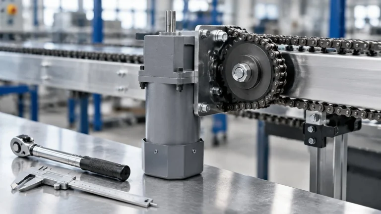
AC Gear Motor with Speed Control: Wiring, Speed Range and Torque Loss
Ngày đăng: Tác giả: Lisa
An AC gear motor with speed control is the cheapest way to make a fixed-speed machine adjustable. A conveyor that must run at two rates, a filling head that needs to ramp, a turntable that has to be tuned on commissioning — all of these are commonly solved by putting a controller in front of an ordinary AC gear motor rather than paying for a servo.
But the controller does not behave like a throttle. It changes the motor’s slip, and slip comes at a cost in torque, heat and stability. Buyers who expect “10% speed, 10% torque” end up with a drive that stalls at the low end and runs hot at the high end. This guide covers what a controller actually does to an AC gear motor, the real speed and torque window, how to wire it, and when the correct answer is a different kind of drive entirely.
Three ways to vary the speed of a gear motor
Before wiring anything, confirm which of these you are actually buying, because they are not interchangeable.
Phương pháp
Works on
Speed range
Torque behaviour
Phù hợp nhất cho
Voltage / phase-angle controller (TRIAC)
Single-phase speed-control or reversible AC motors, 6–120 W typically
About 90–1400 r/min at 50 Hz at the motor shaft
Falls sharply at low speed
Light, continuous loads needing a modest adjustment
Wide, commonly 10–100% of base speed in constant torque
Holds torque down to base speed if the motor can dissipate the heat
Three-phase drives, higher power, real process control
DC or brushless DC gear motor with controller
DC geared motors
Wide, and cheap to implement
Good at low speed; brushes wear
Battery systems, small machines, frequent speed changes
The mistake to avoid is buying a voltage controller for an ordinary single-phase induction gear motor. A plain induction motor on a variable voltage does not hold speed — it drifts with load, hunts at low settings, and can stall. Voltage control only works properly on a motor designed for it.
How a voltage controller actually slows an induction motor
An induction motor’s speed is set by the supply frequency and by slip. Reducing the voltage increases slip, and increased slip reduces speed. That is the whole mechanism, and it explains both why the controller is cheap and why it has limits.
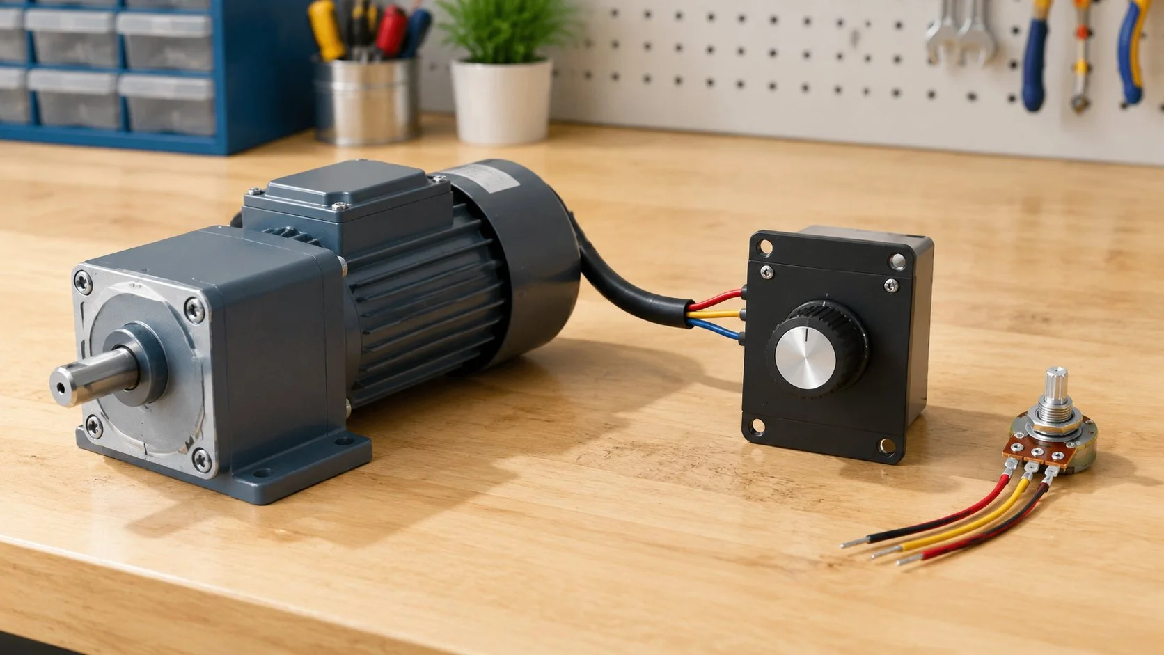
The cheap part: phase-angle control switches the TRIAC once per half cycle, so there is no DC bus, no large capacitor and almost no switching noise. The controller is a small box with a dial and a potentiometer terminal, and it costs a fraction of an inverter.
The limit: an induction motor’s torque is proportional to the square of the applied voltage. Halve the voltage and you have a quarter of the torque. Below a certain voltage the motor moves onto the unstable part of its speed-torque curve, where a small load increase causes a large speed drop or a stall. That is exactly the behaviour buyers complain about when they fit a cheap dimmer-style controller to a standard motor.
This is why speed-control motors carry a small tachogenerator on the shaft. The tacho generates a few cycles per revolution — 12 per revolution is a common figure — and the controller compares that signal with the dial setting every half cycle, adjusting the firing angle to close the gap. The loop is closed, so the motor runs stably down to about 90 r/min and holds speed within roughly ±1% of setting from no load up to the permissible torque. On an uncontrolled motor the equivalent figure is more like −6% to −10%. The tacho is the difference between a speed control motor and a motor with a dimmer in front of it.
The speed range is not the torque range
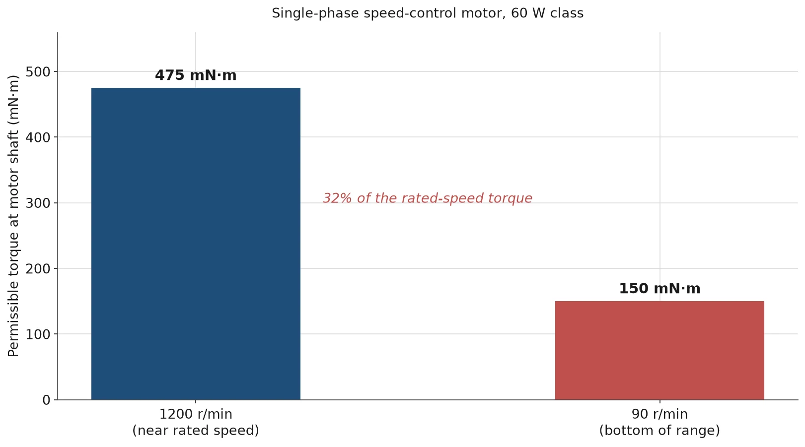
The headline “90–1400 r/min” is a speed range, not a usable working envelope. Torque falls as speed falls, and the fall is steep. Published figures for a 60 W single-phase speed-control motor illustrate it.
Motor shaft speed
Permissible torque
Relative to the 1200 r/min value
1200 r/min
≈460–490 mN·m
100%
90 r/min
≈140–160 mN·m
About 30%
Read that as a rule rather than a curiosity: at the bottom of the speed range you have roughly a third of the torque you had near rated speed. If the machine needs its full load torque at 20% speed, a voltage controller will not deliver it, and no amount of dial adjustment will change that. The correct fix is a higher gear ratio — run the motor fast where it is efficient and let the gearbox produce the slow output speed.
There is also a published safe-operation line for continuous duty at low motor speed. Running near the bottom of the range for long periods overheats the motor because its own fan turns slowly and self-ventilation collapses. Intermittent use at 90 r/min is fine; eight hours a day at 90 r/min is not.
The comparison also sets the practical buying logic. A 40 W fixed-speed unit at a 20:1 ratio produces about 4.3 N·m at 75 r/min all day without complaint. A speed-controlled 40 W drive asked to do the same job at 75 r/min of motor shaft speed would be running near the bottom of its range with a fraction of its torque. Same power, same speed, completely different reliability — because the second one got there by throttling and the first one got there by gearing.
Wiring the controller to the motor
A speed controller installation has four connection groups, and getting the capacitor group wrong is the most common field error.
Supply. Single-phase 220 V (or 110 V for the matching unit) into the controller’s input terminals, with the protective earth landed on both the controller chassis and the motor frame.
Motor leads. Three conductors from the controller to the motor — one common, one main winding, one auxiliary winding. The run capacitor sits across the auxiliary circuit as specified on the motor nameplate; the capacitance value must match the motor, not the controller.
Potentiometer. Three wires to the speed-setting input. Keep this run short or screened; a long unscreened potentiometer lead picks up mains noise and produces a speed that drifts.
Direction. Either a switch on the controller or an external contactor that changes the winding connections. Reversing a capacitor-run motor at speed produces a large current spike, so the control logic should stop the motor, wait for it to come to rest, then reverse.
Supply  L / N / PE  →  controller input
Motor   U / V / W   →  motor terminal box (capacitor per nameplate)
Pot     three wires →  speed setting input
Reverse switch or external contactor, with a standstill dwell before reversing
Voltage drops along the motor cable matter more than usual on a controller installation, because the controller’s output is already reduced at low settings. A long thin run to a motor set at 30% speed can put the winding below the point where it will start at all. Keep the controller close to the motor, and size the cable for the full-load current rather than the reduced current.
Which motors can be speed controlled
This is the question that decides whether the project works, and the answer is narrower than most catalogues suggest.
Motor type
Speed control by voltage controller?
Reason
Speed-control motor (with tachogenerator)
Yes — this is what it is built for
Closed-loop feedback holds speed and prevents stalling
Reversible motor (30-minute rating)
Sometimes, with the matching controller
Short-time duty; continuous low-speed running overheats it
Plain single-phase induction gear motor
No, not reliably
No feedback; speed drifts with load and it stalls at low settings
Three-phase gear motor
No — use a VFD instead
Voltage control on three-phase is not a practical speed method
DC / brushless DC gear motor
Yes, with its own DC controller
Different controller architecture; speed set by armature voltage or commutation
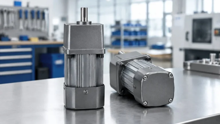
Our own compact AC gear motor range is a fixed-speed induction family. Where a machine genuinely needs variable speed, the honest route is either a matched speed-control motor package or a three-phase unit with a VFD — not a controller bolted onto a standard unit. The electrical differences between the phase types that make this matter are covered in our phase and frequency guide.
Three-phase speed control: the VFD route
Above the small frame — from about 400 W upward — the drive is three-phase and the controller is a VFD. Three practical differences from the voltage controller matter.
Torque holds down to base speed. A V/f drive maintains flux by reducing voltage with frequency, so the motor produces rated torque all the way down to its base speed instead of losing it in proportion to voltage squared. That is why a VFD can run a loaded conveyor at 20% speed and a voltage controller cannot.
Cooling is the new limit. The motor’s own fan is on the shaft. At 25% speed it moves very little air, so continuous operation at low speed and full torque overheats the winding even though the torque is available. Above roughly 2:1 speed reduction, specify an inverter-duty motor with separate forced ventilation, or accept a lower continuous torque.
The drive must match the supply. A 400 W three-phase gear motor needs a three-phase VFD; a single-phase-input VFD that synthesises three-phase output must be derated, and the motor must tolerate the longer cable and higher switching frequency. On a 400 W medium-frame drive the panel space and heat dissipation of the VFD are no longer negligible line items in the project.
When the fault is a worn armature, not the controller
On DC geared motors the speed controller varies armature voltage, and the parts that wear are mechanical: commutator, brushes and bearings. A drive that loses speed stability, judders at low setting or draws more current for the same output is often suffering from a glazed or pitted commutator, worn brushes, or bearing drag on the armature rather than a failed controller board.
The diagnostic order is cheap before expensive. Check that the armature turns freely by hand with power off. Look at the brush length against the wear limit. Inspect the commutator surface for pitting and clean it if needed. Only then suspect the electronics. Our cánh quạt của bộ điều khiển tốc độ is a replacement component for exactly this case — precision-wound copper windings, laminated core to limit eddy-current loss, and a balanced rotor to keep vibration out of the speed loop. Confirm the frame size and mounting dimensions before ordering, because the armature must match the existing stator and end shields.
Mistakes that repeat in speed-controlled installations
Sai lầm
Điều gì sẽ xảy ra
Fix
Fitting a voltage controller to a plain induction gear motor
Speed drifts with load; stalls at low settings
Use a speed-control motor with tacho feedback, or a VFD
Expecting full torque at 100 r/min
Machine stalls near the bottom of the range
Increase the gear ratio and run the motor fast
Running at minimum speed for hours
Winding overheats from lost self-ventilation
Stay above the safe-operation line, or add forced cooling
Mismatched capacitor
Low torque, hot motor, poor starting
Use the capacitance on the motor nameplate
Reversing at speed
Current spike, mechanical shock through the gearbox
Stop, dwell, then reverse
Long unscreened potentiometer lead
Speed drifts and jumps
Short run or screened cable
Controllers are accessories to a drive, not a substitute for selecting one. If the speed range, the duty and the mounting are already fixed, the remaining accessories — torque arms, flanges, couplings and mounting kits — are collected in the Hướng dẫn về phụ kiện động cơ giảm tốc.
Kết luận
A speed-controlled AC gear motor works well inside a narrow, honest envelope: light to moderate loads, speeds above roughly 30% of rated, single-phase power up to about 120 W, and a motor that was designed to be controlled. Outside that envelope the correct answer is a higher gear ratio, a three-phase drive with a VFD, or a DC/brushless unit.
Tell us the speed range, the load torque at the slowest speed you need, and the supply you have — we will say whether a controller is the right mechanism for your machine or whether the ratio should change instead. A 90 W unit with a matched ratio often replaces a smaller speed-controlled drive and gives more usable torque for less money.
Câu hỏi thường gặp
Can I use a dimmer or a fan regulator to control a gear motor?
No. A lamp dimmer is not rated for an inductive motor load, and even a proper voltage controller needs a motor with tachogenerator feedback to hold speed. A plain induction gear motor on a dimmer will stall or overheat.
What speed range can I realistically get from a single-phase controller?
About 90 to 1400 r/min at the motor shaft on 50 Hz, but usable torque at the low end is roughly a third of the 1200 r/min value. Plan on running above about 300 r/min for continuous duty.
Why does my speed-controlled motor lose torque at low speed?
Because a voltage controller reduces speed by increasing slip, and torque falls roughly with the square of applied voltage. The gearbox multiplies whatever torque remains, which is why a higher ratio is usually a better answer than a lower setting.
Can I speed control a three-phase gear motor with a voltage controller?
Not practically. Use a VFD, which varies frequency as well as voltage and holds torque down to base speed. Check that the motor can dissipate heat at the minimum speed you intend to run.
Does a speed controller work in both directions?
Many controllers include a forward/reverse selector, but the motor must be reversible-rated and the control logic must allow a standstill dwell before reversing. Reversing at speed produces a large current spike and a torque shock through the gearbox.
When is a DC gear motor the better choice for variable speed?
When the supply is DC or battery, when very low speeds are needed continuously, or when the speed must change often. The trade-off is brush and commutator wear — the armature becomes a service part, which is why replacement armatures are stocked for these drives.
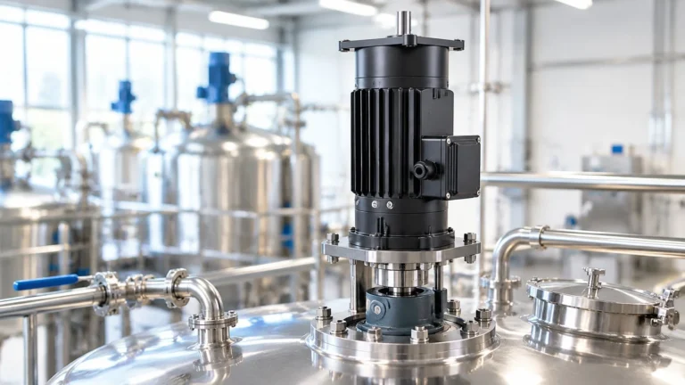
Agitator drives fail on starting torque and thrust load, not on kilowatts. How to calculate impeller power, convert it to shaft torque, and where a gear motor stops being the right drive.
The 30-minute rating on a reversible gear motor is a thermal statement, not a timer. What it limits, how to read your duty cycle against it, and how to run longer without buying the wrong motor.
Five steps from a machine to a torque number: converting load to force, force to shaft torque, correcting for gearbox efficiency, applying a service factor, and checking the result against the allowable load table.