Gear Motor Size Chart: Frame Sizes, Dimensions & Torque Specifications
Published: Author: Lisa
Choosing the wrong frame size is the single most common reason a gear motor returns from a trial fit. The motor may run, but the bolt circle, shaft height, or torque output does not match the driven machine, and you end up re-machining brackets or sourcing a new unit. A reliable gear motor size chart ties frame number to physical footprint and to the power, speed, and torque envelope so you can pick the right unit before you order. This guide shows how to read the chart, what dimensions actually control fit, and which Tenchuan series to choose for the most common small-frame jobs.
What Is a Gear Motor Frame Size?
A frame size is a coded number — usually the motor body diameter in millimetres for small AC gear motors, or a NEMA/IEC number for industrial units — that locks together the four dimensions you need to mount the unit:
Motor body diameter (or faceplate width for NEMA).
Shaft height from the mounting base to the output shaft centreline.
Pilot diameter on the front flange (for flange- or face-mounted units).
Bolt-circle pattern on the base or flange.
Because those four dimensions are fixed by the frame, the same frame can usually accept a range of output powers, gear ratios, and shaft speeds. That is also why you can drop a 60 W motor into a machine that previously ran a 40 W unit on the same frame, without re-machining the bracket. See our small AC gear reducer motor line for current frame and power combinations.
How to Read a Gear Motor Size Chart
Every size chart answers three questions in this order:
What frame fits? Match the body diameter, shaft height, and bolt circle to your existing bracket or coupling.
What power does the frame support? The same frame usually covers a power band (for example 15 W to 40 W on a 60 mm frame, 40 W to 90 W on a 90 mm frame).
What output torque and speed result? These depend on the gearbox ratio and the motor’s rated speed. Always read the rated torque at the output shaft, not at the motor shaft.
Two units with the same frame but different gear ratios will have different output torque at the same input power, so when comparing charts, compare like-for-like at the output shaft.
Standard Small AC Gear Motor Frame Sizes
The most common small AC induction gear motor frames are 60 mm, 70 mm, 80 mm, 90 mm, and 104 mm body diameter. Each frame covers a power band and a typical torque envelope:
Treat these as planning bands, not absolute limits. Real torque depends on the gear ratio you select; a 90 mm frame at 10:1 will deliver very different torque from the same frame at 60:1.
Real Frame Data From the Tenchuan 5RK 60 W Series
To make the chart concrete, here is the rated output data for the Small AC Gear Reducer Motor 60 W on the 90 mm frame. All values are taken from the published nameplate data for that model.
Motor Model
Duty
Output Power
Voltage
Current
Rated Torque
Rated Speed
5RK30GN-C
Reversible 30 min
60 W
1-phase 220 V
0.50 A
670 mN·m (67 kg·cm)
1350 r/min
5RK30A-C
Reversible 30 min
60 W
1-phase 220 V
0.52 A
554 mN·m (55.4 kg·cm)
1550 r/min
5RK30GN-A
Reversible 30 min
60 W
1-phase 110 V
1.00 A
670 mN·m (67 kg·cm)
1350 r/min
5RK30GN-S
Reversible 30 min
60 W
3-phase 220 V
0.52 A
441 mN·m (44.1 kg·cm)
1350 r/min
Same frame, four supply variants. This is exactly why a frame-based size chart works: pick the frame, then choose the voltage and duty that match your site supply.
Key Dimensions That Control Fit
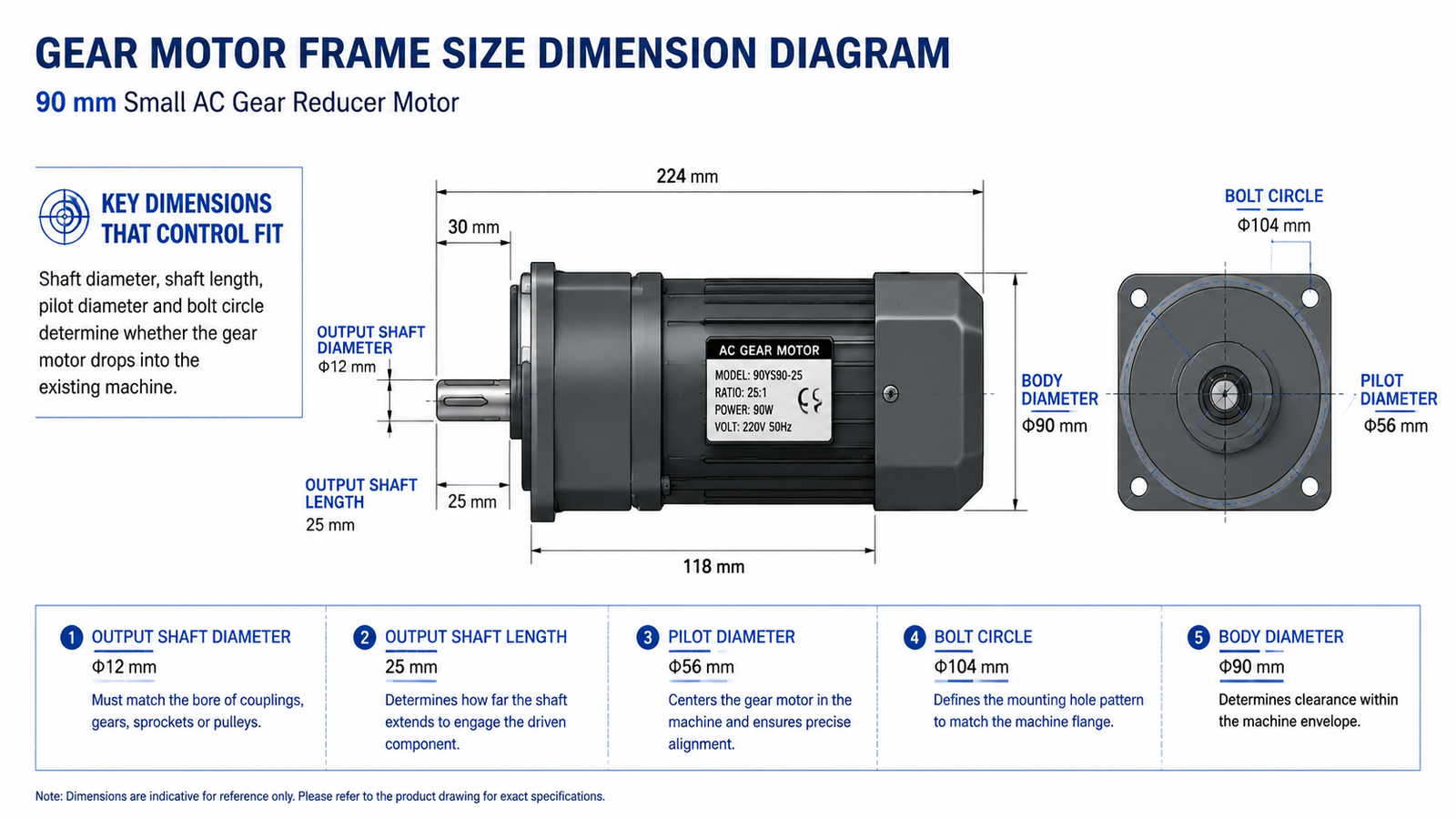
Beyond the chart values, four dimensions decide whether a gear motor drops into your machine:
Shaft diameter: Must match the coupling, sprocket, or pulley bore. Common sizes are 6, 8, 10, 12, and 15 mm.
Shaft length: Allows the coupling to seat fully. Short shafts force the coupling onto the shoulder and may cause axial preload.
Pilot diameter: The spigot on flange-mounted units that locates concentricity. Mismatch causes vibration at speed.
Bolt-circle diameter and foot pattern: Determines whether the existing bracket can be re-used. Always confirm in millimetres, not by NEMA “frame size” alone.
For a deeper look at how the motor and gearbox halves share the same envelope, our gear motor parts identification guide shows which dimensions belong to which side of the assembly.
Mounting Configurations
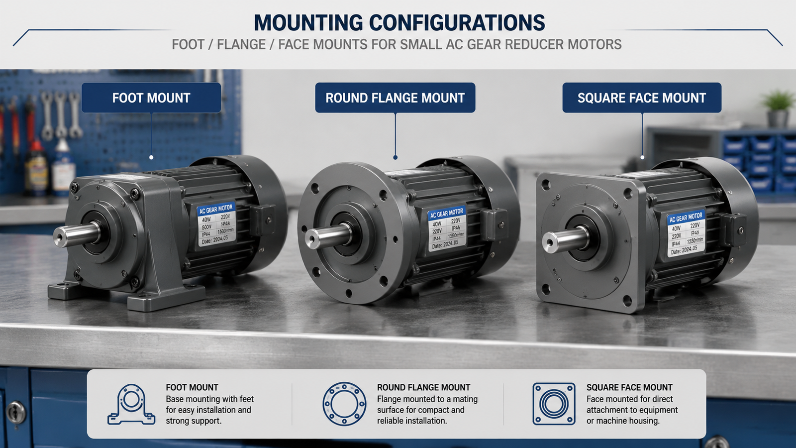
Three mounting styles cover most small AC gear motor installations:
Foot mount: Bolts to a base plate. Easiest to align and re-level. Best for conveyors and packaging lines.
Flange mount: Bolts through a round flange on the gearbox front face. Saves axial space and holds concentricity, ideal for fans, agitators, and mixers.
Face mount: Square flange on the gearbox. Used where the driven shaft must be parallel to the mounting surface, common on right-angle gear reducer motors.
The matched accessories — torque arms, couplings, flanges, and base kits — are summarised in our gear motor accessories guide.
Gear Ratio and Its Effect on Output Torque
Gear ratio multiplies motor torque at the output shaft, at the cost of output speed. The relationship is roughly:
Output torque ≈ Motor torque × Ratio × Gearbox efficiency
For a 60 W motor at 1350 r/min on a 90 mm frame, the published allowable load at common ratios is:
Ratio
5:1
10:1
20:1
30:1
50:1
100:1
180:1
300:1
Allowable load (N·m)
1.08
2.64
4.80
6.24
9.64
14.4
19.6
19.6
Approx. output speed (r/min)
270
135
67
45
27
13
7.5
4.5
Notice that beyond about 180:1 the allowable load flattens — gearbox torque capacity, not ratio, is the limit. For ratios above 200:1, install a second reduction stage between motor and gearbox, or pick the next larger frame.
How to Choose the Right Frame Size
Use this five-step process before you commit to a frame:
Calculate load torque: Multiply the load by its radius (T = F × r). Add a 1.5× service factor for shock loads, vertical lifts, or frequent start-stop duty.
Set required output speed: Speed (r/min) = Driven input speed / Gear ratio. Choose ratio to match.
Pick the smallest frame that meets both: Smallest compliant frame keeps cost and inertia down.
Verify the duty cycle: Reversible, continuous, or short-time ratings are not interchangeable. The 5RK 60 W is rated for reversible 30-minute duty, not continuous S1.
Confirm the environment: IP rating, ambient temperature, and mounting orientation all constrain the choice. If you are unsure, our small AC gear motor selection guide walks through each step with worked examples.
Common Frame Size Mistakes to Avoid
Picking by power alone. A 90 W motor on a 60 mm frame may fit electrically but exceed the frame’s mechanical torque limit.
Ignoring the duty rating. A reversible 30-minute motor run continuously will overheat, even if the rated torque matches.
Mixing unit systems. Chinese and Japanese datasheets usually use mm; NEMA datasheets use inches. Confirm before drilling brackets.
Forgetting pilot concentricity. A 1 mm pilot mismatch causes vibration well above 1000 r/min, even when the bolt circle lines up.
Stacking two small frames instead of one right-sized frame. Two gearboxes in series introduce backlash and cost more than one properly sized unit. For typical applications, see our types of gear motors overview to pick the right topology before sizing.
FAQ
What does the frame size number actually mean?
For small AC induction gear motors, the frame number is the motor body diameter in millimetres. A 90 mm frame has a 90 mm body diameter and a fixed shaft height, pilot diameter, and bolt-circle pattern across all models on that frame.
Can I swap a 40 W motor for a 60 W motor on the same frame?
Usually yes. The 5RK 40 W and 5RK 60 W share the same 90 mm frame, so the mounting dimensions match. Confirm the rated torque, duty cycle, and supply voltage before swapping, and verify that the driven machine can accept the higher output torque.
How do I convert rated torque between N·m, kg·cm, and mN·m?
Use the conversions 1 N·m ≈ 10.2 kg·cm, and 1 N·m = 1000 mN·m. Always read rated torque at the output shaft, not at the motor shaft, when comparing gear motors.
What gear ratio should I choose for a slow-output application?
For output speeds below 10 r/min, choose a frame one size larger than the chart suggests and stay within the published allowable load for that frame. Ratios above 200:1 on a single stage reduce efficiency and raise backlash; consider a two-stage reduction instead.
Does the frame affect the IP rating?
Frame size and IP rating are independent. A 60 mm frame motor can carry IP65 sealing just as easily as a 104 mm frame. The IP rating is set by the seal design and the cable entry, not by the body diameter.
Conclusion
A good gear motor size chart saves a round of bracket re-machining. Match the frame first (body diameter, shaft height, pilot, bolt circle), then read the published rated torque for your chosen ratio, and finally confirm duty cycle and supply. When you are ready to specify a unit, send Tenchuan your required output speed, load torque, supply voltage, and mounting style — we will match the frame and ratio against the chart above and confirm the right model on the same day.
Practical guide to selecting a gear motor for door openers: calculate required torque and output speed, understand self-locking worm gear drives, and match the right AC gear motor to your door type.
Selection guide for gear motors used in hospital beds, infusion pumps, ventilators, lab equipment and other medical devices. Covers noise, precision, IEC 60601-1 safety, IP rating and self-locking requirements, plus a step-by-step selection workflow and application table.