Parallel-Shaft vs Right-Angle Gear Motor: Which Fits Your Machine
Right-angle vs inline gear motor compared with real allowable load tables: efficiency, torque, the self-locking myth and how to decide in five steps.
Read More
A 750W gear motor is one horsepower in practical terms, and at that size the mounting orientation stops being a drawing detail and becomes a design decision. The same unit mounted horizontally on a conveyor base and mounted vertically over an agitator tank sees different oil levels, different bearing loads, different seal exposure and a different cooling path. Buyers who choose vertical simply because the layout is tight usually find out within a month, when the output seal starts weeping onto the product.
This guide covers the 750W medium frame — 28 mm output shaft, 3-phase 220 V or 380 V, vertical or horizontal configuration — and explains what actually changes between the two orientations, how to calculate the torque you will get at each ratio, and the checks to run before you commit the mounting to the machine drawing.
750W is approximately 1 HP, which is why this class attracts buyers searching for a one-horsepower gear motor. Output torque is not fixed by the power rating; it follows from the ratio, and it has to be calculated rather than read off a single number.
Output torque (N·m) = 9550 × P (kW) × η / n (r/min)

P = 0.75 kW
η = gearbox efficiency, typically 0.85–0.92
n = output speed = motor rated speed ÷ ratio| Ratio | Output speed at 50 Hz | Calculated output torque (η = 0.90) |
|---|---|---|
| 5:1 | 280 r/min | 23.0 N·m |
| 10:1 | 140 r/min | 46.0 N·m |
| 15:1 | 93 r/min | 69.3 N·m |
| 20:1 | 70 r/min | 92.1 N·m |
| 30:1 | 47 r/min | 137.2 N·m |
| 50:1 | 28 r/min | 230.2 N·m |
| 60:1 | 23 r/min | 280.3 N·m |
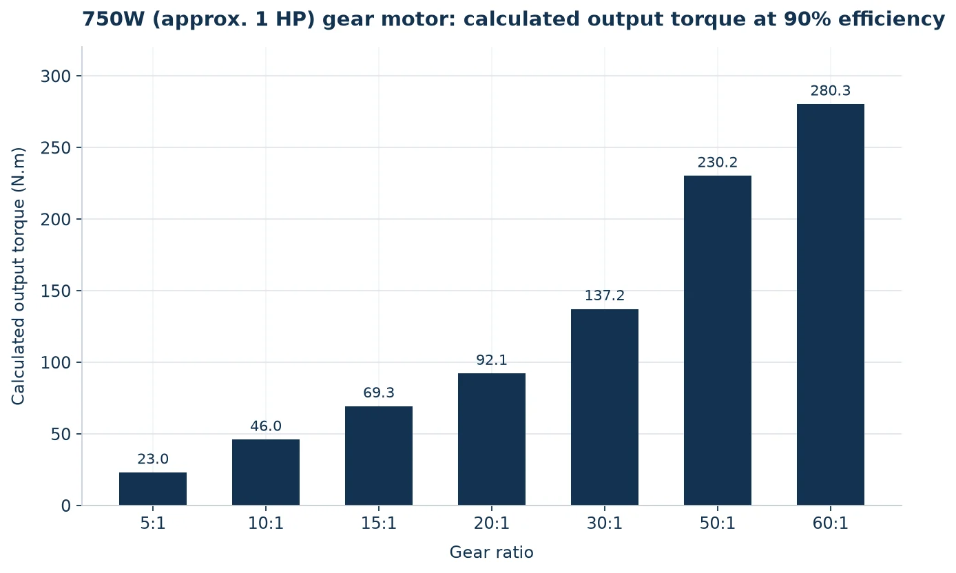
These are the theoretical capability of a 750W input at 90% efficiency, before any service factor. The gearbox’s own allowable output torque can be lower at high ratios, and it must be confirmed for the specific model. Treat the table as the ceiling you calculate against, not the rating you order to.
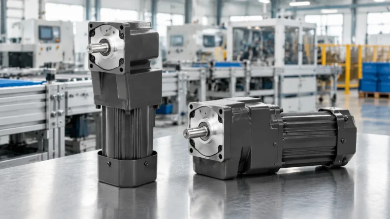
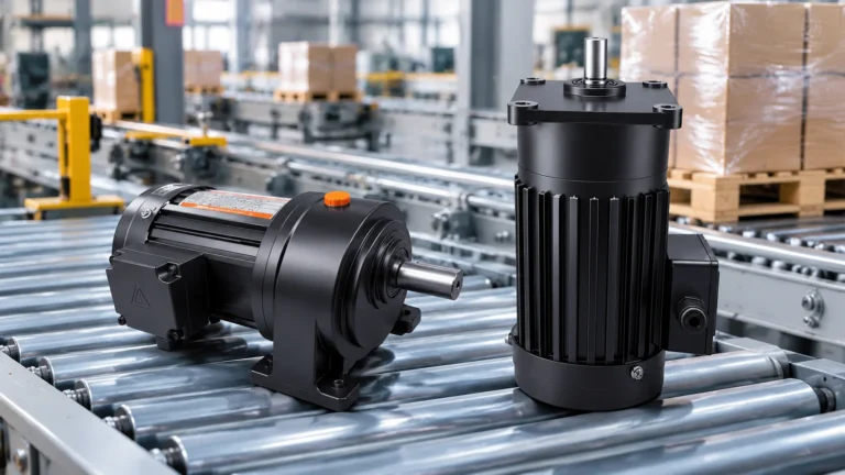
In this range, vertical and horizontal are two configurations of the same power class, and the difference is the relationship between the motor axis and the gearbox output shaft. In a horizontal unit the output shaft is parallel to the mounting surface, which suits conveyor head shafts, line shafts and machine base drives. In a vertical unit the output shaft points up or down, which suits agitators, mixers, vertical screws, rotary tables and any machine where the driven shaft is vertical.
What does not change is the motor, the 28 mm output shaft diameter, the 3-phase 220 V / 380 V supply or the power rating. What changes is everything around them:
| Aspect | Horizontal mounting | Vertical mounting |
|---|---|---|
| Driven shaft direction | Parallel to base, side drive | Vertical, top or bottom drive |
| Lubricant level | Level relative to gearbox centreline | Level relative to the gearbox axis; plugs move |
| Output seal exposure | Side, mostly drained | Faces down and stays wetted, or faces up and collects ingress |
| Bearing load | Mainly radial from the drive element | Radial plus the axial weight of the shaft and driven part |
| Motor position | Beside the gearbox, low centre of gravity | Above or below, raising or lowering the centre of gravity |
| Cooling air path | Undisturbed around the fan cowl | Often obstructed by the machine frame or tank top |
| Condensation risk | Moderate | Higher at the upper bearing on a vertical motor |
The right order is: establish the direction of the driven shaft, choose the configuration that matches it, then solve the space problem around that choice. Doing it in the other order is what produces a horizontal unit squeezed into a vertical shaft application through a pair of bevel or chain drives — which adds a second reduction, adds efficiency loss, adds backlash and adds a maintenance point, all to avoid ordering the correct configuration.
There is one legitimate case for going against the driven shaft: when the shaft direction can be changed cheaply at the driven end, for example a belt drive where the pulleys can be arranged either way. In that case choose the orientation that gives the better structure, which is almost always horizontal.
Medium frames are commonly oil-lubricated rather than grease-packed, and oil-lubricated gearboxes have their fill, level and drain points arranged for a particular mounting orientation. A unit filled to the horizontal mark and then installed vertically will either overfill the lower bearing cavity — pushing oil past the output seal — or leave the upper bearing starved.
Three checks prevent this. Confirm with the supplier which orientation the unit was filled for and whether the same casting serves both. Confirm the position of the level plug for your orientation, because on many units it must be relocated or a different plug used. And confirm the oil grade and quantity for the installed orientation, not for the catalogue figure, since the two often differ by a few hundred millilitres at this size.
The broader relationship between service factor, backlash and lubrication is covered in service factor, backlash and lubrication in an electric motor gearbox.
On a vertical unit with the output facing down, the lip seal sits at the lowest point of the gearbox and oil is permanently against it. Any wear, any grit on the shaft, any slight runout and the result is a slow drip — straight onto the product, the tank or the floor. On a vertical unit with the output facing up, the same seal faces the opposite problem: washdown water, dust or product spillage runs down the shaft into it.
Practical countermeasures are simple and cheap. Fit a slinger or deflector disc on the shaft above the seal. Keep the shaft surface under the lip free of keyway edges and burrs. Where washdown is present, specify a higher protection rating and arrange a drip shield over the shaft. And on any vertical drive, add seal inspection to the maintenance schedule at the same interval as the oil check — a weeping seal caught early is a five-minute fix, and caught late it is a gearbox rebuild.
In a horizontal unit the output bearing mainly resists radial load from the sprocket, pulley or coupling. In a vertical unit the same bearing also carries the dead weight of the output shaft and whatever hangs from it — an agitator impeller, a screw flight, a rotary table platen — plus any axial process force such as the upward thrust of a mixer blade pushing through a viscous product.
Two consequences follow. The overhung load limit you would apply to a horizontal unit is not the right limit for a vertical one, because the axial component is additive. And a driven element that is heavy but radially well-supported — a long agitator shaft with a steady bearing — can still overload the gearbox if the steady bearing is misaligned, because the gearbox then carries a bending moment it was never designed for. Support the shaft at the far end, align it to the gearbox axis within the coupling’s allowance, and use a flexible coupling rather than a rigid one.
Accessory options including flanges, couplings and torque arms are described in the gear motor accessories guide.
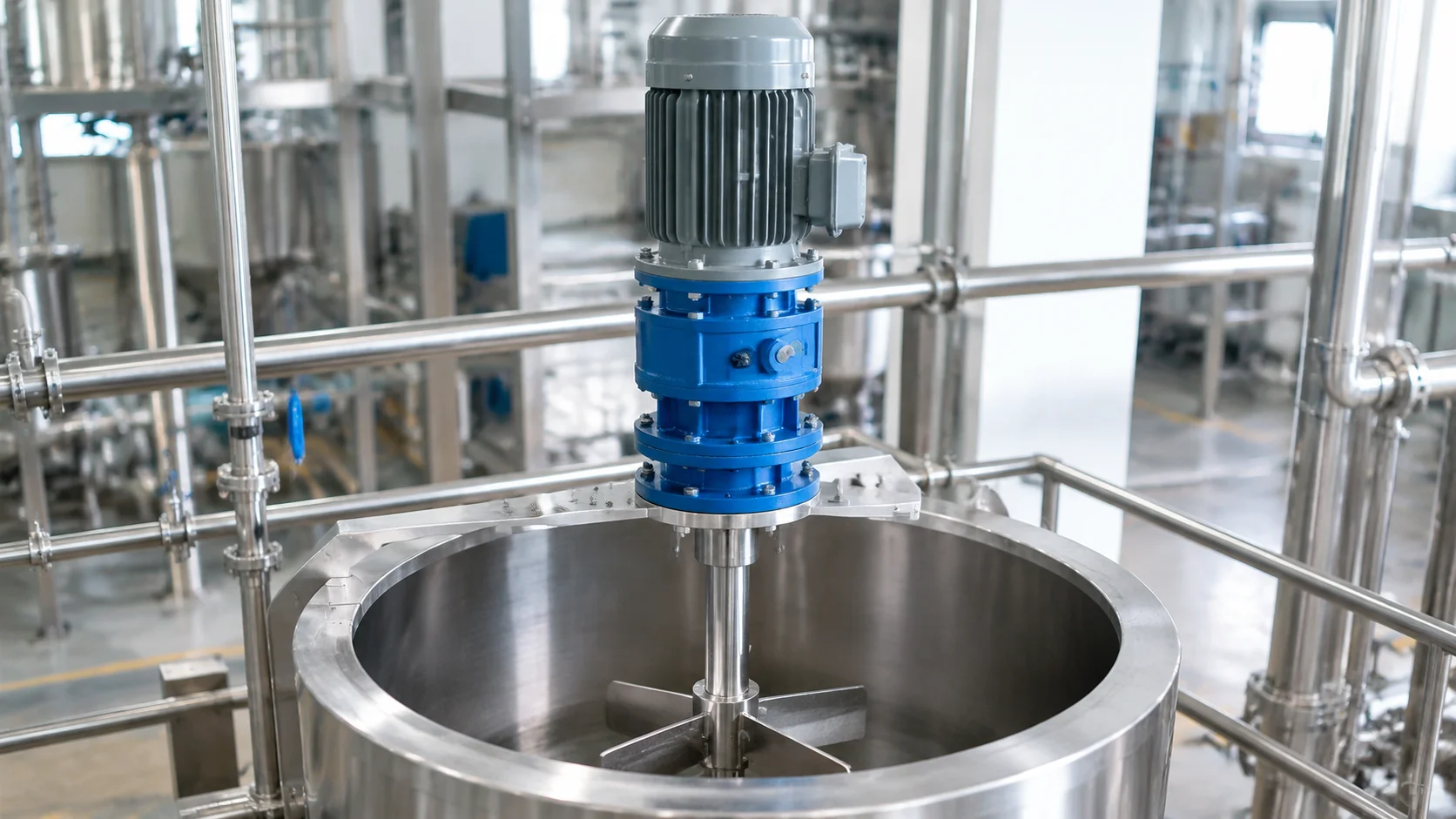
The 28 mm output shaft is the practical reason many buyers choose 750W over 400W. At this diameter a keyed coupling carries the torque comfortably, but three details decide whether the drive lasts. Key and keyway fit should be a light interference, not a loose slip fit. The coupling must be rated for the calculated torque with a service factor, not for the motor power. And runout at the coupling must be checked with a dial gauge after assembly, because a vertical shaft with a long overhung element amplifies any misalignment into vibration at the top of the machine.
On a vertical unit the motor is usually above the gearbox. That placement has three side effects worth designing for. The fan cowl must have clear air on all sides; a motor tucked under a tank top or inside a frame will run hot and lose torque margin. The terminal box should be positioned so the cable entry faces down, so water cannot track along the cable into the box. And the upper bearing of a vertical motor is the place where condensate collects in humid or washdown environments, so either specify a drain arrangement or plan a periodic run cycle that warms the motor through.
Where ambient temperature exceeds about 40 °C, or the motor sits in an enclosure, derate the selection. A 750W drive chosen at its calculated torque with no margin will lose that margin entirely in a hot enclosure.
If the calculated torque, ratio and service factor still need work, the method is set out in gear reducer sizing with a worked example.
Vertical mounting is not a space-saving trick. If the driven shaft is horizontal and the only problem is side clearance, a vertical unit adds a change of direction that has to be solved somewhere else in the drivetrain, usually with a chain or bevel set that costs more than the clearance saved. Two situations justify staying horizontal: when the machine structure cannot carry the weight of a vertical unit above it without flexing, and when the driven element needs frequent removal, because a vertical arrangement usually means lifting the motor to service the shaft.
If your requirement has outgrown the 750W class, the next step is the 1500W medium frame, which keeps the same vertical and horizontal logic at double the torque. Below it, the 400W model uses a 22 mm shaft and is the right answer for lighter duty on the same electrical supply.
Send: required output speed in r/min; load torque, or mass and radius; whether the driven shaft is vertical or horizontal and which way it faces; duty cycle with starts per hour and reversing; supply voltage and phase, 220 V or 380 V three-phase; ambient temperature and any washdown exposure; shaft, keyway and flange requirements; and the driven element type, since an agitator and a conveyor of the same torque need different service factors.
The 750W AC gear reducer motor page lists the 28 mm standard shaft, both configurations, the 3-phase voltage options and the dimension drawing for each orientation, so the mechanical fit can be confirmed before a ratio is fixed.
Approximately 1 HP (0.75 kW). Buyers searching for a 1 HP gear motor usually land in this class, with a 28 mm output shaft and 3-phase 220 V or 380 V supply.
It depends on the ratio. Calculated at 90% efficiency, a 750W input gives about 46 N·m at 10:1, 137 N·m at 30:1 and 230 N·m at 50:1. Confirm the gearbox allowable load for the ratio selected.
Yes, a vertical configuration is available alongside the horizontal one. The unit must be filled and configured for vertical orientation, and the output seal and thrust load need specific attention.
No. Power, ratio and shaft diameter are unchanged. Orientation changes lubricant level, seal exposure, bearing loading and cooling, not the drive’s speed or torque rating.
Usually because the oil level suits horizontal mounting, or because the downward-facing lip seal is worn or damaged by grit on the shaft. Correct fill level plus a shaft slinger and a clean shaft surface prevents most cases.
Yes. A flexible coupling tolerates the small misalignment that a long vertical shaft inevitably has, and prevents the gearbox bearing from carrying a bending moment it was not designed for.
Choose vertical or horizontal from the direction of the driven shaft, then solve the space problem around that decision rather than through it. On a vertical 750W unit, confirm the oil fill and level plug for the orientation, protect the output seal, add the axial load to your bearing check, and keep the fan cowl and terminal box clear. The motor, ratio and 28 mm shaft are the easy part; the mounting is where these drives succeed or fail.