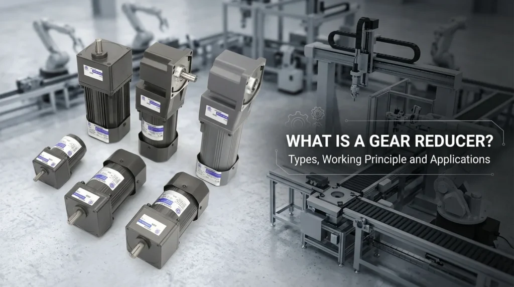
Gear Reducer Types Working Principles and Applications
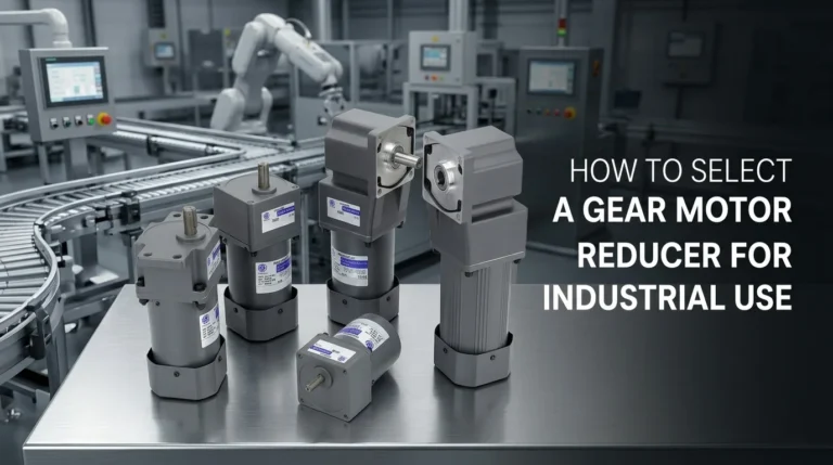
What Is a Gear Reducer? The Core Mechanics and Working Principle
In my years of sizing equipment for heavy industry, I constantly hear operators asking: Why can’t I just connect a high-speed motor directly to my conveyor belt? The reality is that standard motors spin far too fast and lack the raw pushing power to move heavy loads from a dead stop. This is where mechanical power transmission steps in. A gear reducer acts as the essential middleman, safely transforming rapid, low-power motor rotations into slow, heavy-lifting force.
The Math Behind the Motion: Speed-to-Torque Ratio
The entire working principle of a gear reducer hinges on a strict inverse relationship: as rotational speed (RPM) decreases, output torque increases. In the industry, we call this torque multiplication.
When performing a reduction ratio calculation, you are directly measuring how the gearbox manages motor energy conversion.
- The Calculation:
Ratio = Input Speed / Output Speed - The Concept: The ratio dictates exactly how many times the motor must spin to rotate your machinery just once.
- The Real-World Impact: If you install a reducer with a 10:1 reduction ratio, the motor turns ten times for every single revolution of the output shaft. You sacrifice ten parts of speed to gain roughly ten times the structural moving power.
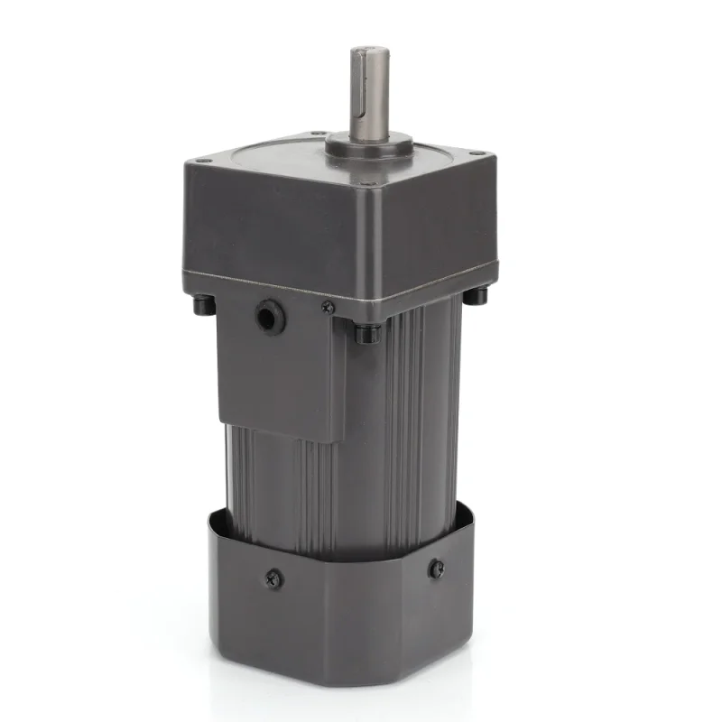
Internal Anatomy of a Reducer
To grasp how this power shift happens, you only need to understand the critical internal components that carry the load. While outer housings vary by application, every reliable gearbox relies on this basic anatomy:
- Input and Output Shaft: The high-speed motor physically drives the input shaft. After the internal gears do their job, the heavy-duty output shaft delivers the newly multiplied torque directly to your machinery.
- Gear Stages: This is where the actual speed reduction happens. Depending on your required ratio, a reducer might use a single gear mesh or multiple interlocking stages to aggressively step down the speed.
- Industrial Bearings: Extreme torque multiplication creates massive physical stress inside the housing. High-grade bearings are utilized to stabilize the shafts, reduce friction, and keep the gear stages perfectly aligned under heavy radial and axial loads.
What Is a Gear Reducer? Main Types and Characteristics
Choosing the right gear reducer boils down to matching your specific shaft configuration and load requirements. We rely on five main types to handle power transmission across demanding global industries. Here is exactly what you need to know about their unique advantages.
- Planetary Gear Reducers
Built with a coaxial setup, these units pack excellent load distribution into a highly compact footprint. We use them primarily when an application demands high precision without taking up excess space. - Worm Gear Reducers
This is your go-to for a reliable orthogonal gear setup. They are cost-effective and feature natural self-locking properties, meaning the output shaft cannot be back-driven by the load. When configuring 90-degree machinery, utilizing a robust AC right-angle gear reducer motor offers both built-in safety and incredible value. - Helical Gear Reducers
Functioning as a parallel shaft reducer, helical gears utilize angled teeth to guarantee smooth, low-noise operation. They are highly favored for their massive transmission efficiency, consistently reaching up to 95%. - Bevel Gear Reducers
Bevel reducers also redirect power at a 90-degree angle, but they do so using intersecting axes. We rely on them when the drive direction must change without sacrificing transmission efficiency. For more compact industrial setups requiring this directional shift, integrating a small AC gear reducer motor keeps the footprint tight while maintaining high performance. - Cycloidal Gear Reducers
The cycloidal drive mechanism is built for extreme, heavy-duty environments. It provides exceptional shock resistance and zero-backlash capabilities, allowing the machinery to absorb massive operational spikes without failing.
Key Performance Metrics for Sizing and Selection
Getting the right gear reducer isn’t just about matching physical dimensions; it’s about looking hard at the operating numbers. When I spec out a power transmission system, I focus strictly on these core performance metrics to ensure long-term reliability and cost-effectiveness.
Transmission Efficiency & Gearbox Backlash
The internal gear design directly controls how well power moves from the motor to the driven machine.
- Transmission Efficiency: This measures how much of the original motor energy conversion actually reaches your application. High efficiency minimizes energy loss. For instance, when integrating a 200W small AC gear reducer motor, optimizing your transmission efficiency ensures you extract every bit of usable torque from that specific power rating without wasting electricity on internal friction.
- Gearbox Backlash: This is the slight gap or play between mating gear teeth. While a tiny amount of clearance is necessary for smooth running, excess play ruins positioning accuracy. If your application requires precise stops and starts, keeping backlash as close to zero as possible is mandatory.
Thermal Limits and Overload Capacity
Friction creates heat, and unmanaged heat will ultimately destroy machinery.
- Respecting Thermal Limits: Every unit operates safely only within the established thermal limits of gearboxes. Running a system continuously past these temperature boundaries rapidly breaks down the gearbox lubrication and sealing, guaranteeing early failure.
- Handling Operational Spikes: Your reducer must have enough overload capacity to absorb sudden torque spikes. Even when dealing with lighter automation tasks powered by a 140W small AC gear reducer motor, the gearbox needs the durability to handle unexpected mechanical jams or abrupt load shifts without shearing a gear.
Common Industrial Applications of Gear Reducers
In our experience supplying global manufacturing lines, reliable mechanical power transmission is the backbone of modern production. Gear reducers are the silent workhorses making this happen. From delicate robotic movements to massive assembly lines, here is where we see them applied most effectively:
- Automation and Robotics: Precision is everything. We rely on high-precision planetary and cycloidal reducers to deliver pinpoint accuracy and seamless mechatronics integration. They easily handle the rapid stops, starts, and exact positioning that modern robotic arms demand.
- Material Handling and Conveyors: Moving goods efficiently requires consistent, reliable power. For these systems, reliable helical and worm gear implementations are the industry standard. In lighter sorting lines or automated packaging stations, integrating a compact small AC gear reducer motor 90W delivers the perfect balance of steady speed and space-saving efficiency.
- Heavy Machinery and Packaging: These highly demanding environments run entirely on torque multiplication. Whether driving industrial mixers, massive presses, or continuous packaging machinery, you need durable, high-torque setups. These reducers are built tough to handle intense operational spikes and massive loads without breaking a sweat.
Installation and Maintenance Best Practices
Getting your gear reducer set up correctly and keeping it well-maintained is just as critical as selecting the right model. Proper care ensures smooth mechanical power transmission and maximizes the operational lifespan of your entire drive system.
Mounting Configurations
When integrating gear motors and accessories into your machinery, the physical installation typically comes down to two primary shaft configurations:
- Solid Shaft Mounting: This traditional setup uses external couplings to connect the reducer’s solid output shaft to the driven equipment. While highly robust for heavy-duty applications, it requires precise shaft alignment to prevent vibration and premature wear.
- Hollow Shaft Mounting: This space-saving method allows the reducer to slip directly onto the driven machine’s shaft. It eliminates the need for bulky couplings, makes installation faster, and significantly reduces alignment issues.
Gearbox Lubrication and Sealing
Routine maintenance is the best defense against unexpected downtime. Effective gearbox lubrication and sealing keep the internal components moving efficiently while preventing damaging friction and heat buildup.
Follow these standard maintenance steps to keep your reducer running smoothly:
- Use the Right Oil Viscosity: Always match the lubricant viscosity to your specific operating environment. Thicker oils are necessary for high-temperature operations, while thinner oils prevent sluggishness during cold starts.
- Stick to Maintenance Schedules: Routinely check oil levels and change the lubricant at recommended intervals. Fresh oil flushes out microscopic metal shavings and prevents gear degradation.
- Inspect and Protect Seals: Regularly inspect oil seals for weeping or hardening. Worn seals allow critical lubricant to leak out and harmful contaminants to enter. Replacing them early is a low-cost way to prevent total gearbox failure.
Whether you are maintaining a single conveyor line or implementing comprehensive industrial drive solutions, adhering to these straightforward installation and maintenance practices will keep your equipment reliable and efficient for years.