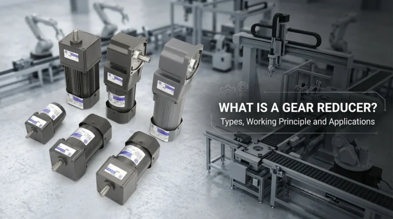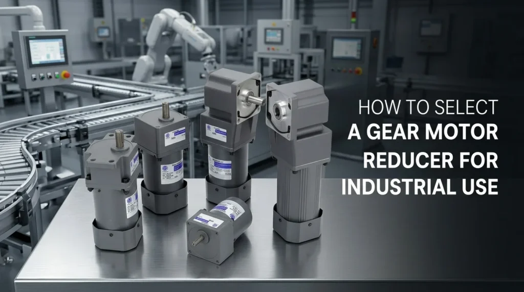
How to Select an Industrial Gear Motor Reducer Guide
Step 1: Define Your Baseline Application Requirements
Are you worried about under-sizing your drive and facing a catastrophic failure on the production line, or over-sizing and destroying your equipment budget? I hear this concern from facility managers and fellow engineers every day. As industry professionals, we know that learning how to select a gear motor reducer for industrial use starts with nailing the physics from day one. If you skip over the baseline application requirements, the rest of this industrial gearbox selection guide won’t save you.
Calculate Output Torque and RPM
The absolute heart of motor gearbox combination sizing is understanding the relationship between horsepower (HP), torque, and speed (RPM). You need to know exactly how much twisting force your application demands to move the load efficiently.
I always have my team run the raw numbers first. Absolute accuracy at this stage guarantees long-term reliability in the field. Here are the standard engineering formulas you must use to calculate output torque:
| Measurement System | Input Power | Formula for Torque |
|---|---|---|
| Imperial (US) | Horsepower (HP) | Torque (lb-in) = (HP × 63,025) / RPM |
| Metric | Kilowatts (kW) | Torque (Nm) = (kW × 9,550) / RPM |
- Speed (RPM): The final operational speed required at your driven shaft.
- Input Power: The mechanical power required to actually do the work.
- Torque: The rotational force. Remember the golden rule of power transmission: as speed drops through mechanical reduction, torque increases proportionally.
Gearbox Reduction Ratio Formula
Once you have defined your required output speed and torque, you must determine the exact gear reduction ratio. This specification dictates exactly how much the gearbox will slow down the motor to multiply your torque.
The gearbox reduction ratio formula is straightforward and foundational for any drive system:
- Ratio = Motor Input RPM ÷ Desired Output RPM
Real-World Application:
If you are running a standard 4-pole AC motor at 1,750 RPM and your conveyor’s head pulley needs to spin at exactly 70 RPM, the math is simple:
1,750 ÷ 70 = 25
You require an exact 25:1 reduction ratio.
Getting these baseline numbers right is non-negotiable for system longevity. When you run into a complex motor gearbox combination sizing problem, our engineering team relies on precision data to solve it fast. We pride ourselves on accuracy, reliability, and the 24-hour speed of service required to calculate these specs and keep your operation moving without delay.
Step 2: Apply the Correct AGMA Service Factor
When figuring out how to select a gear motor reducer for industrial use, calculating the baseline specs is only half the battle. You have to account for real-world wear and tear. This is where the AGMA service factor comes into play—it is essentially your built-in safety margin to ensure long-term reliability.
Assessing the Duty Cycle
First, I always evaluate how long the equipment will actually run. A motor running three hours a day experiences vastly different stress than a machine running non-stop.
- Intermittent Operation: Lower overall stress, usually requiring a standard service factor (around 1.0).
- 24/7 Operation: High sustained stress. If your setup runs constantly, you absolutely need a continuous duty cycle gearmotor paired with a higher service factor (1.25 or higher) to prevent premature thermal or mechanical failure.
Accounting for Shock Loads
Next, look at the nature of the load itself. Not every machine runs perfectly smoothly. We categorize mechanical stress into three main buckets:
- Uniform Loads: Smooth, steady operation without sudden spikes. Think lightweight material conveyors or liquid agitators.
- Moderate Shock: Uneven, fluctuating stress. Common examples include multi-cylinder pumps or packaging machinery with frequent starts and stops. If you are building a system with these demands and tight space constraints, integrating a robust 120W-300W AC right-angle gear reducer motor provides the necessary durability to handle these moderate shocks reliably.
- Heavy Shock: Brutal, violent force. Rock crushers, heavy punch presses, and industrial shredders fall here and demand the highest service multipliers to survive.
Always cross-reference your specific application with a standard AGMA service factor table to lock in the exact multiplier. Properly matching your duty cycle and shock load conditions ensures your gearhead life is maximized and your operation doesn’t face unexpected downtime.
Step 3: Analyze Mechanical Loads on the Shaft
When I guide teams on how to select a gear motor reducer for industrial use, I always emphasize the physical forces acting directly on the shaft. Ignoring these mechanical loads is the fastest way to destroy your bearings and halt production. You need to evaluate two main forces to keep your equipment running reliably.
Overhung Load Capacity
Overhung Load (OHL), also known as radial force, happens when external components pull sideways on the output shaft. If you connect sprockets, pulleys, or drive belts to your gearbox, they create a constant bending force.
You must verify the overhung load capacity of the reducer matches your application. For example, if you are driving a heavily loaded conveyor belt using a 200W small AC gear reducer motor, that continuous sideways pull requires robust shaft support. If the radial force exceeds the manufacturer’s rating, the shaft can snap or the bearings will fail prematurely.
Radial and Axial Thrust Loads
While OHL pulls sideways, a thrust load pushes or pulls directly in line with the shaft. This is your axial force. You will typically see high axial forces in applications like mixers, extruders, or screw jacks where the load pushes back into the gearbox.
To protect your system, keep these core load factors in mind:
- Calculate the Sideways Pull (OHL): Always factor in the tension and weight from belts, chains, and pulleys to find your exact radial load.
- Check Bearing Capacity: Ensure the internal bearings are rated to handle both the expected radial and axial thrust loads simultaneously without binding or overheating.
- Size Up for Safety: If your inline pushing or pulling forces are extremely high, you may need to upgrade to a slightly larger unit, such as a 300W small AC gear reducer motor, purely to secure the heavier, reinforced bearings required for the job.
Step 4: Choose the Right Gear Reducer Configuration
When sizing equipment for global industrial use, we know that selecting the right mechanical layout dictates your system’s long-term success. You must balance physical space, budget, and performance. Here is our breakdown of the three primary gearbox configurations to match your specific operational needs.
Worm Gear Reducers
Often deployed as a right angle speed reducer, worm gears provide a simple, highly cost-effective solution for tight budgets and basic machinery.
- Pros: Very low upfront cost, massive reduction ratios in a single stage, and inherent self-locking capabilities that prevent loads from back-driving.
- Cons: Lower mechanical efficiency due to sliding friction. They generate more heat and consume more power during continuous operation.
Helical and Bevel Gears
When maximizing helical gear motor efficiency is the priority, these are the standard choice for heavy-duty industrial environments.
- Pros: Extremely high efficiency (often exceeding 95%), very low noise levels, and robust construction suited for continuous, high-torque duty cycles without overheating.
- Cons: Higher initial investment and a generally larger physical footprint compared to worm drives.
Planetary Gearboxes
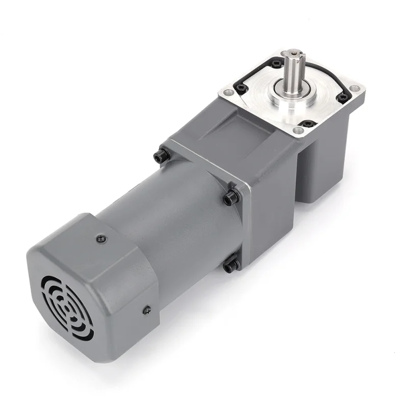
If you are evaluating a planetary vs worm gear reducer, planetary units easily win when installation space is extremely tight but power demands remain high. For instance, when integrating components like a small AC gear reducer motor 120W into compact automation equipment, the planetary design maximizes output while minimizing the machine footprint.
- Pros: The highest torque density available, an extremely compact cylindrical footprint, and superior load distribution across multiple gears.
- Cons: The complex internal engineering typically results in a higher purchase price.
Configuration Comparison
| Gearbox Type | Initial Cost | Efficiency | Torque Density | Ideal Industrial Application |
|---|---|---|---|---|
| Worm | Low | Low (50-80%) | Moderate | Budget-friendly setups, right-angle fits, self-locking needs. |
| Helical/Bevel | Medium | High (95%+) | High | Continuous duty, maximum energy savings, low noise. |
| Planetary | High | High (90%+) | Very High | Confined spaces requiring massive torque output. |
Step 5: Match Physical Mounting and Space Constraints
When I evaluate how to select a gear motor reducer for industrial use, I always prioritize the physical space available on the factory floor or within the machine itself. Even the most powerful gearbox is useless if it simply will not fit into your equipment. The machine footprint directly dictates the physical layout of the drive system.
Machine Footprint Dictation
Depending on how much room you have to work with, you will need to choose a specific layout configuration to maximize efficiency without wasting space:
- Inline Coaxial Gear Reducer: This layout is best for applications where the motor and gearbox need to sit in a straight line. It is an incredibly common and straightforward design, but it does require adequate linear length.
- Right Angle Speed Reducer: Perfect for tight corners and compact machines. The output shaft sits at a 90-degree angle to the motor, saving valuable horizontal space by tucking the motor alongside the equipment.
- Parallel Shaft: Ideal when you need a narrow footprint but the input and output shafts must run in the same direction, allowing the motor to sit side-by-side with the gearbox.
Gear Reducer Mounting Options
How you attach the unit is just as critical as its physical shape. Selecting the correct gear reducer mounting options allows you to secure the drive safely without having to over-engineer your machine’s frame. This is especially true when integrating compact components, like a small AC gear reducer motor 40W, where picking the right mount instantly streamlines the assembly process.
- Foot Mount: The traditional, heavy-duty method. The gearbox bolts directly to a solid baseplate or the floor, providing maximum stability.
- Flange Mount: The gearbox bolts directly to the driven machine’s housing. This ensures perfect alignment and eliminates the need for a separate mounting base.
- Hollow Shaft / Shaft-Mount: The reducer slips directly over the driven shaft of the machine. This eliminates the need for flexible couplings and extra structural supports, making it the absolute most space-efficient choice available.
Step 6: Factor in the Operating Environment
The physical space where your equipment runs is just as critical as the mechanical loads it handles. Ignoring the surrounding environment will drastically reduce your gearhead life. When we build an industrial gearbox selection guide, assessing the operating conditions is always the final, non-negotiable step.
Here is exactly what you need to evaluate:
Thermal Horsepower Rating
When running a continuous duty cycle gearmotor or pushing heavy loads, heat becomes your biggest enemy. Mechanical friction naturally creates thermal energy. If the gear reducer cannot dissipate that heat fast enough, the oil degrades, and the internal components fail.
- Understand the Limit: The thermal horsepower rating tells you exactly how much power the unit can transmit continuously without overheating.
- Prevent Overheating: If your application’s demand exceeds this thermal limit, you must intervene. You will need to either step up to a larger gearbox size, use synthetic lubricants, or install external cooling fans and heat exchangers to keep temperatures in check.
Ingress Protection and Lubrication
Dust, moisture, and extreme temperatures will quickly destroy a gear reducer if it is not properly protected. You must match the unit’s sealing and lubrication strategy to the exact room it operates in.
- Assess the Seals: Standard seals are fine for clean, climate-controlled manufacturing floors. However, if your equipment faces heavy dust, outdoor weather, or aggressive high-pressure washdowns (common in food and pharma), you need specialized seals and a high Ingress Protection (IP) rating. You can explore our targeted industrial gear motor solutions to see which sealing options are best suited for harsh environments.
- Mineral vs. Synthetic Oil: Standard mineral oil is cost-effective and works perfectly for normal ambient temperatures. But if your machinery operates in extreme cold, high heat, or requires long periods between maintenance, upgrading to synthetic oil is the smart, reliable choice.
If you are unsure about matching the right IP ratings and thermal capacities to your facility’s conditions, simply contact our team to verify your specifications before installation.