Parallel-Shaft vs Right-Angle Gear Motor: Which Fits Your Machine
Right-angle vs inline gear motor compared with real allowable load tables: efficiency, torque, the self-locking myth and how to decide in five steps.
Read More
Ask ten suppliers for a “gear reducer” and you will get ten different products, because the word covers everything from a 15 W integrated gear motor on a lab instrument to a 250 kW helical-bevel industrial gear unit bolted to a mine conveyor. This guide stays inside one category: compact integrated AC gear motors in the 15 W to 3.7 kW class, where the motor and reduction gearbox share a single housing and mount as one unit.
Within that class there are only two configurations that matter for selection — parallel-shaft (inline) and right-angle — plus a handful of variations in frame size, ratio and supply. Getting the configuration right first saves more design rework than any torque calculation.
An integrated gear motor has four functional groups in one assembly:
Because everything is in one housing, the unit has no coupling to align, no separate reducer to foot-mount, and one part number to stock. That is the entire commercial argument for integrated gear motors over a motor plus separate gearbox, and it is why they dominate packaging, conveying, dispensing and light automation equipment.
It also means the gearbox and motor share a thermal environment. That constraint drives much of what follows.
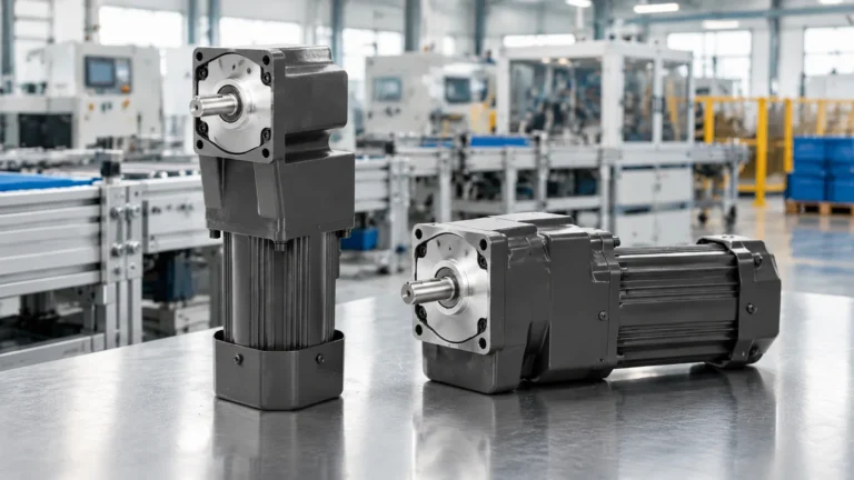
The motor shaft and output shaft are parallel, and the gear train is a stack of spur or helical stages. On our range this is the 4RK (25–30 W, 80 mm frame), 5RK (40–90 W) and 6RK (120–300 W) families.
The output shaft exits at 90° to the motor axis through a bevel or hypoid final stage. On our range this is the 4GN (25 W), 5GU (40–140 W) and 6GU (120–300 W) families.
One clarification worth stating plainly: a right-angle gear motor is not the same thing as a worm gear motor. Worm drives achieve high ratios in a compact right-angle form and can be self-locking, but they run at 40–85% efficiency and are a distinct product. Right-angle bevel units are more efficient and are not self-locking. Confusing the two is the most common cause of a “the door creeps when the power goes off” complaint.
| Property | Parallel-shaft (4RK / 5RK / 6RK) | Right-angle (4GN / 5GU / 6GU) |
|---|---|---|
| Shaft direction | Along motor axis | 90° to motor axis |
| Efficiency per stage | 95–98% | 85–92% |
| Noise at equal speed | Lower | Higher |
| Overall length | Longer | Shorter |
| Layout flexibility | Low | High |
| Self-locking | No | No |
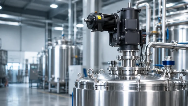
| Best for | Straight conveyor runs, agitators, inline drives | Belt conveyors, door operators, dispensers, tight cabinets |
Configuration sets the geometry; frame size sets the power. In our range the frames step cleanly:
| Frame | Power | Series | Typical shaft |
|---|---|---|---|
| 70 mm | 15 W | 4RK / 4GN | Small, light-load stations |
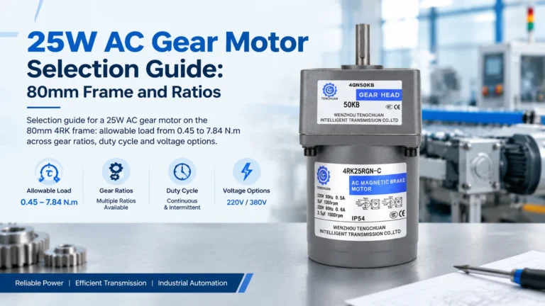
| 80 mm | 25–30 W | 4RK / 4GN | Carousels, gates, small conveyors |
| 90 mm | 40–90 W | 5RK / 5GU | Packaging, indexing, medium conveyors |
| 90 mm heavy | 120–300 W | 6RK / 6GU | Case handling, heavy infeed |
| Medium frames | 400–3700 W | Vertical / horizontal | 22–50 mm output shaft, three-phase |
Two things change at the 400 W boundary: the supply becomes three-phase 220V/380V as standard, and mounting becomes a genuine vertical-or-horizontal decision rather than a bracket detail. Above 3.7 kW you have left this product class entirely and are in industrial gear unit territory.
Ratio is chosen from output speed, not from a wish for more torque. On the 25 W 4RK, the catalogue runs from 3:1 (500 r/min) to 300:1 (5 r/min), and the allowable load plateaus:
| Ratio | Output speed (rpm) | Max allowable load |
|---|---|---|
| 3:1 | 500 | 0.45 N·m |
| 10:1 | 150 | 1.55 N·m |
| 30:1 | 50 | 4.12 N·m |
| 100:1 | 15 | 7.84 N·m |
| 300:1 | 5 | 7.84 N·m — no further gain |
Past roughly 100:1 the gearbox becomes the limit and additional ratio buys only lower speed. Anyone who needs more torque than the plateau at a given frame must change frame, not ratio.
Parallel-shaft is more efficient, quieter and better for overhung loads. Right-angle is shorter and gives layout freedom. Choose right-angle only when the machine geometry actually needs a 90° turn — otherwise take the efficiency.
They are parallel-shaft series in ascending frame size and power: 4RK covers 25–30 W on an 80 mm frame, 5RK covers 40–90 W, and 6RK covers 120–300 W. The 4GN / 5GU / 6GU equivalents are the right-angle versions of the same power tiers.
Not from our range. Above 3.7 kW the market moves to separate motor-and-reducer assemblies with oil lubrication and AGMA or ISO service classification — a different product category.
No. Bevel and hypoid right-angle stages back-drive freely. Only worm gearboxes achieve self-locking, and even then only at low lead angles.
Type selection usually follows the load. For light machinery up to 300W, the small AC gear reducer motors range covers 4RK, 5RK and 6RK frames; above that, the medium gear reducer motors series runs from 400W to 3700W with output shafts up to 50mm. Where the gearbox has to turn the drive through 90 degrees, the right angle gear reducer motors use a bevel configuration instead of a parallel shaft.
The small gear motor selection page compares frame sizes and ratios side by side, and the 6GU right angle gear reducer motor is a practical example of the 90-degree arrangement in the 120W–300W band.
If you want the type confirmed against a specific duty, send the details through our contact form.
When you are replacing an existing drive rather than specifying a new one, the nameplate and type code tell you the type before you measure anything. A 4GN, 5GU or 6GU prefix indicates a right-angle (bevel) unit in our range; 4RK, 5RK or 6RK indicates a parallel-shaft unit. The number before the letters is the frame size, which scales with power.
That matters because the two types are not interchangeable in a machine: a right-angle unit changes where the output shaft exits, so the mounting face and available depth have to be checked as well. Our right angle gear reducer motors page lists the 90-degree options, and the small AC gear reducer motors page groups the parallel-shaft frames.
Conveyors and packaging lines usually take a parallel-shaft unit where there is room along the frame, or a right-angle unit where the drive has to sit under the belt. Turntables, mixers and gate operators more often need the 90-degree exit. Above 300W, the medium gear reducer motors series uses the same logic at 400W-3700W.
Send a photo of the nameplate and the machine layout through the contact form if you want the type confirmed.