Parallel-Shaft vs Right-Angle Gear Motor: Which Fits Your Machine
Right-angle vs inline gear motor compared with real allowable load tables: efficiency, torque, the self-locking myth and how to decide in five steps.
Read More
Service factor is the most misunderstood number in gear motor selection. Buyers treat it as a safety blanket — “add 1.5 and we are covered” — and suppliers quote torque figures that quietly assume a different operating condition. On the industrial side, service factor comes from AGMA conventions designed for large reducers running continuously. Below about 4 kW, on compact integrated AC gear motors, the governing limits are different: they are thermal first and mechanical second, and the number that matters is not the AGMA factor but the rated duty printed next to the torque.
This guide covers how to add margin correctly on integrated AC gear motors from 15 W to 3.7 kW — the range this factory actually builds.
An AGMA service factor is applied to the transmitted power to account for shock loading and duty class, then used to select a reducer size from a catalogue rated for continuous operation in a defined environment. It works well when the reducer is a separate unit with an oil sump, a published thermal rating and an external motor.
An integrated compact gear motor is a different animal:
So the correct method is: use a service factor to establish a required output torque, then verify that torque against the allowable load at your ratio and against the duty rating at your cycle time. Skipping the second step is how a drive that “looked fine on paper” runs at 95 °C in the field.
Three categories cover almost everything in the compact range:
| Duty class | Typical application | Starting service factor |
|---|---|---|
| Uniform | Centrifugal fan, small conveyor with steady feed, agitator on low-viscosity fluid | 1.0–1.2 |
| Moderate shock | Reciprocating feeder, indexing table, packaging station, start-stop conveyors with uneven loading | 1.3–1.5 |
| Heavy shock | Auger in compacted material, jam-prone gate, crusher feed, rapid reversing axis | 1.7–2.0 |
Two rules that prevent most oversizing and undersizing errors:
Work from the load, never from the motor nameplate:
Trequired = Tload × SF
For rotary loads, Tload comes from friction, gravity and process resistance. For a horizontal conveyor:
Tload = (Ffriction + Fincline) × rpulley
For a lifting or incline axis, add the gravity term and remember that starting from rest requires the static friction coefficient, not the dynamic one.
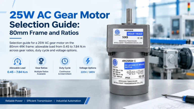
This is the step that gets skipped. On a fixed frame size, allowable output load rises as the ratio rises and output speed falls — so the same motor can be under-rated or over-rated depending purely on the ratio you chose for speed. Real data for the 25 W 4RK on an 80 mm frame:
| Ratio | Output speed (rpm, 50 Hz) | Max allowable load | Mechanical limit reached? |
|---|---|---|---|
| 3:1 | 500 | 0.45 N·m | No |
| 10:1 | 150 | 1.55 N·m | No |
| 30:1 | 50 | 4.12 N·m | No |
| 50:1 | 30 | 6.18 N·m | Approaching |
| 100:1 | 15 | 7.84 N·m | Yes — gearbox ceiling |
| 300:1 | 5 | 7.84 N·m | Yes — no further gain |
The practical consequence: you cannot buy your way out of a torque deficit with more ratio. Past roughly 100:1 on this frame the gearbox is the limit, and going to 200:1 or 300:1 only reduces speed. If the required torque exceeds 7.84 N·m, move to the 40 W, 60 W or 90 W frame.
A gear motor can be mechanically fine and thermally overloaded at the same time. Three checks:
Our small AC series is rated reversible 30 min for reversing duty and continuous for one-direction running. Reading these as interchangeable is the single most common specification error in the range. A packaging station that indexes one way continuously is a continuous load; a gate that opens and closes is a reversible load.
At 50% duty the winding heats during the run and partially cools during the pause. At 90% duty it barely cools at all. As a working rule for small totally-enclosed units, once run time exceeds about 70% of cycle time, treat the application as continuous regardless of what the duty table says.
Standard ratings assume roughly 40 °C ambient. In a Southeast Asian plant with an unventilated enclosure, internal air can sit at 50–55 °C. Derate the allowable load by roughly 1% per °C above 40, and more aggressively inside a sealed cabinet. This matters far more in tropical installations than the service factor conversation does.
Torque is only half the mechanical story. A pulley, sprocket or gear mounted out on the output shaft applies a bending moment to the gearbox bearing:
Equivalent overhung load = (2 × T ÷ d) × Kf
with T output torque, d the pulley or sprocket pitch diameter, and Kf a factor of 1.0 for a gear, 1.25 for a chain sprocket and 1.5 for a V-belt. Keep the load close to the housing face. If you cannot, add a support bearing on the shaft end rather than uprating the gearbox — uprating does not fix a moment problem efficiently.
A packaging line infeed conveyor carries 40 kg of product at 0.35 m/s on a 60 mm pulley. Belt friction coefficient 0.15, and the belt must restart loaded several times an hour.
Note that step 6 required the catalogue table, not a formula. Every compact gear motor selection ends the same way.
1.0–1.2 for uniform loads, 1.3–1.5 for moderate shock, 1.7–2.0 for heavy shock. Then verify the resulting torque against the allowable load at your chosen ratio and against the duty rating. The factor alone is not a selection.
No. It means the gearbox must be rated for 1.5 times the calculated load torque, which is not the same as 50% more power capability once thermal limits and gearbox ceilings are applied.
Because the gearbox, not the motor, becomes the limiting component. On our 25 W frame the allowable load plateaus at 7.84 N·m from about 100:1 upward. Beyond that point additional ratio only reduces speed.
Yes. Standard ratings assume about 40 °C. Above that, derate allowable load by roughly 1% per °C, and more inside a sealed enclosure. In tropical plants this is often the deciding constraint.