7 Types of Gear Motor Key Differences Explained
The main types of gear motor can be classified in two ways: by the electric motor that supplies the power and by the gears that transmit it.
Read More
To select gear motors correctly, start at the driven load: define the required output speed, continuous and peak torque, duty cycle, power supply, mounting, shaft loads, and operating environment. Then calculate an initial reduction ratio, choose a suitable gear motors and gearbox type, apply the required service margin, and verify mechanical and thermal ratings. Selecting by voltage or wattage alone can produce a drive that is too slow, too weak, oversized, or prone to overheating.
| Selection input | What to define | Why it matters |
|---|---|---|
| Driven load | Conveyor, mixer, lift, feeder, wheel, or other mechanism | Determines load behavior and service requirements |
| Output speed | Required rpm at the final driven shaft | Sets the approximate reduction ratio |
| Torque | Continuous, starting, acceleration, reversing, and peak torque | Determines motor and reducer capacity |
| Duty cycle | Run time, rest time, starts per hour, and operating hours per day | Affects temperature and design life |
| Power and control | AC/DC, voltage, phase, frequency, speed range, brake, feedback | Ensures electrical and controller compatibility |
| Mechanical interface | Shaft, mounting, orientation, envelope, radial and axial loads | Prevents fit and bearing-load failures |
| Environment | Temperature, dust, water, chemicals, altitude, and noise limits | Determines enclosure, lubricant, materials, and derating |
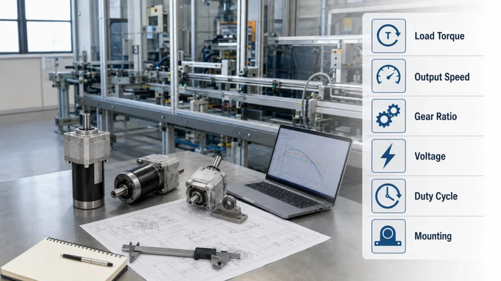
Begin with the machine function rather than a product catalog. Record the desired linear or rotational speed, load mass, pulley or wheel diameter, acceleration time, incline, friction, and any external transmission ratio. A conveyor starting full, a mixer moving viscous material, and a gate exposed to wind may require much more starting or peak torque than their steady running load suggests.
Separate continuous torque from short-duration peak torque. Also identify shock loads, jams, emergency stops, frequent reversals, and whether the load can drive the motor backward. These conditions influence the gear motors size, gear design, brake requirement, and service factor.
Specify rpm at the gearbox output shaft—not the unloaded motor speed. If a conveyor is described by belt speed, calculate pulley rpm from belt speed and pulley circumference. If sprockets, chains, pulleys, or gears sit after the reducer, include their ratio as well.
An initial reducer ratio can be estimated as:
Reduction ratio = rated motor speed ÷ required gearbox output speed
For example, a motor rated near 1,500 rpm and an output requirement of 50 rpm suggest an initial ratio near 30:1. Actual rated motor speed may vary with load, frequency, motor design, and control method, so verify the available output speeds in the manufacturer’s data.
A reducer trades speed for torque, but it does not create power. A first estimate is:
Output torque ≈ motor torque × ratio × gearbox efficiency
Use this relationship for early sizing only. Final selection must remain within the published rated output torque. The gearbox has losses, and efficiency changes with gear type, ratio, speed, temperature, lubricant, and load.
Apply the manufacturer’s specified service factor or application factor for duty hours, starts, load variation, and shock. Continuous-duty equipment normally needs more margin than a lightly loaded intermittent mechanism. Confirm both the required running torque and the worst credible peak torque without treating the maximum or emergency rating as a continuous rating.
A gear reduction motor 12V is usually a DC solution for battery-powered equipment, mobile robots, small vehicles, actuators, and portable machinery. Specify rated and peak current as well as voltage. The power supply, battery, controller, fuse, wiring, and connector must tolerate starting current without excessive voltage drop.
A gear reduction motor 220V is commonly considered for mains-powered industrial equipment. Confirm whether the supply is single-phase or three-phase and whether it operates at 50 or 60 Hz. Also specify reversible operation, braking, and speed control. The gear motors nameplate and controller must match the actual electrical system; “220V” by itself is not a complete specification.
For compact industrial AC applications, review Tenchuan’s Small AC Gear Reducer Motors to compare available frame sizes, power levels, voltages, and ratios.
A gear reducer is a gearbox used to reduce speed and multiply torque. The terms reducer and speed reducer gearbox are frequently used interchangeably, but the construction can differ substantially:
| Reducer type | Useful characteristics | Selection considerations |
|---|---|---|
| Spur | Simple, economical, compact | Noise and backlash may matter at higher speed or during reversal |
| Helical | Smooth tooth engagement and strong continuous-duty capability | Axial thrust and bearing design must be considered |
| Worm | Large reduction in a compact right-angle layout | Sliding losses, heat, and back-driving behavior require verification |
| Bevel or hypoid | Efficient right-angle power transmission | Precision, lubrication, and shaft loads affect performance |
| Planetary | High torque density and coaxial packaging | Greater complexity and typically higher cost |
Choose the gear architecture from shaft direction, available space, efficiency, noise, backlash, load, and cost requirements. Never assume that a worm unit is safely self-locking; if holding a load is safety-critical, use a correctly rated brake or holding system.
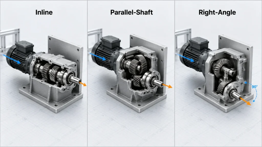
Confirm the mounting face, bolt pattern, output shaft diameter and length, key or flat, shaft direction, terminal-box or cable orientation, and available installation space. Check whether the specified mounting orientation is permitted because lubrication can depend on position.
A pulley, sprocket, pinion, or helical mechanism can apply radial or axial force to the output shaft. Compare calculated loads with the reducer’s allowable overhung and thrust-load ratings at the actual load location. Moving a pulley farther from the bearing increases bending load even when transmitted torque stays the same.
Mechanical torque capacity is not the only limit. Continuous running, a warm enclosure, low-speed motor operation, frequent starts, or high losses can cause excessive temperature even when peak torque is acceptable. Verify ambient temperature, ventilation, insulation rating, reducer thermal capacity, and permitted duty.
If an AC motor uses a variable-frequency drive, confirm the approved frequency range and cooling at low speed. A shaft-mounted fan becomes less effective as motor speed falls. Some applications require a separately powered fan or a different motor-and-ratio combination.
Define whether the machine needs adjustable speed, soft starting, frequent reversing, controlled deceleration, a brake, encoder feedback, limit switches, or torque limiting. The controller must suit the motor technology, voltage, current, and required operating mode.
Do not rely on motor holding torque or reducer friction as the sole safety measure for suspended loads or hazardous motion. Brakes, guards, emergency stops, overload protection, and machine-level risk controls should be engineered for the application and applicable standards.
Power rating is a useful catalog filter after the load requirements are known. Compact mechanisms may begin with a 25W small AC gear reducer motor. A light conveyor may move the comparison to a 60W model, while higher output requirements can be evaluated against a 120W model or a 200W model.
Units with the same wattage can deliver different output torque and speed because the gearbox ratio and capacity differ. Always check the combined geared-drive rating rather than matching only the motor power.
A capable gear motors supplier should request application data before recommending a model. Evaluate the clarity of drawings and performance tables, quality controls, sample support, inspection documentation, lead times, communication, and replacement availability. For repeat orders, ask how component and process changes are controlled.
The Products section shows Tenchuan’s available drive categories, while About Tenchuan provides background for company evaluation. Compare suppliers against one standardized requirement sheet so quotations cover equivalent voltage, ratio, torque, mounting, accessories, testing, packaging, and commercial terms.
Gear motors customization may be appropriate when a standard unit cannot satisfy voltage, winding, output speed, shaft, flange, mounting, cable direction, connector, brake, encoder, terminal box, branding, or packaging requirements. Customization can improve machine integration but may increase engineering time, tooling, minimum order quantity, and lead time.
Before approving a custom model, freeze a controlled drawing and specification that states rated conditions, tolerances, test methods, acceptance criteria, labeling, and change-control requirements. Test representative samples under real load before authorizing volume production.
The best drive is the smallest correctly rated unit that meets the load’s speed, torque, duty, thermal, mechanical, electrical, environmental, and safety requirements with an appropriate margin. Begin at the output shaft, document every assumption, and validate the selected unit in the real machine. Visit the Tenchuan home page for an overview or contact Tenchuan with your completed requirement sheet for model, ratio, and customization guidance.
Divide the rated motor speed by the required gear motors box output speed, then account for any external belt, chain, or gear reduction and choose the closest available ratio that meets torque requirements.
Start with required output speed and continuous and peak torque. These define output power and guide the motor-reducer combination.
A higher ratio increases theoretical torque and lowers speed, but output remains limited by efficiency, gearbox capacity, motor power, thermal conditions, and the required operating speed.
Use the manufacturer’s method for the machine type, duty hours, starts, shock, and operating conditions. Service-factor systems are not always interchangeable between brands.
No. Confirm AC or DC, single-phase or three-phase, 50 or 60 Hz, allowable voltage range, wiring, and controller compatibility.
Provide output rpm, continuous and peak torque, voltage, phase, frequency, duty cycle, mounting, shaft loads, environment, controller, brake or feedback needs, available space, quantity, and customization requirements.