Choosing a small gear reducer motor starts with the load, not the motor catalog. Define the required output speed, continuous and peak torque, duty cycle, available space, mounting arrangement, and power supply. Then select the reduction ratio and motor power that meet those conditions with a reasonable service margin. This method prevents the two most common mistakes: choosing by wattage alone and assuming that a higher gear ratio automatically solves every torque problem.
This guide gives machine designers, OEM buyers, and maintenance teams a practical selection process for conveyors, packaging equipment, labeling machines, feeders, and other compact automation. If you are new to the product family, Tenchuan’s Home page provides an overview of its compact drive range.
What Information Do You Need Before Selecting a Motor?
A supplier can make a useful recommendation only when the application data is clear. Record the operating requirements before comparing models:
Required output speed: the target revolutions per minute at the driven shaft.
Load torque: the torque needed during normal operation, acceleration, and any jam or shock condition.
Duty cycle: continuous or intermittent operation, daily running hours, starts per hour, and reversing frequency.
Power supply: voltage, frequency, phase, and whether a speed controller or inverter is required.
Mechanical interface: shaft diameter and direction, mounting orientation, coupling method, and available envelope.
Use these inputs to compare the available Small AC Gear Reducer Motors rather than starting with the smallest housing or the lowest price.
Step 1: Calculate Output Speed and Reduction Ratio
The gear ratio determines how far motor speed is reduced. Begin with the rated motor speed at the actual supply frequency and the required output speed:
Reduction ratio = motor speed (rpm) / required output speed (rpm)
For example, if a motor runs at 1,500 rpm and the machine needs approximately 50 rpm, the calculated ratio is 30:1. Select the nearest standard ratio, then verify the catalog’s rated output speed because motor slip, load, frequency, and gearbox efficiency can change the real result.
Do not select the ratio from the desired conveyor speed alone. Convert linear speed into drive-shaft rpm using the roller or pulley diameter. Also check whether a controller is intended for fine adjustment. A controller can provide flexibility, but it should not compensate for a fundamentally incorrect mechanical ratio or prolonged low-speed operation that causes overheating.
Step 2: Determine Torque and Apply a Service Factor
Output torque must cover steady running resistance and the highest expected demand. For a conveyor, this includes conveyed mass, friction, incline, pulley radius, acceleration, and transmission losses. For a feeder or indexing mechanism, starting torque and repeated stops may be more important than steady-state torque.
A simplified relationship is:
Estimated output torque = motor torque × ratio × gearbox efficiency
Use this only for an initial estimate. Final selection should be checked against the manufacturer’s rated allowable torque for the exact motor, gearhead, ratio, and duty. Apply a service factor for frequent starts, reversing, shock loads, long running hours, or uncertain friction. A motor that barely meets the calculated average torque may stall during acceleration or experience shortened gear and bearing life.
Application condition
Selection focus
Risk if ignored
Steady light conveyor
Continuous torque, speed, and thermal rating
Overheating during long shifts
Frequent start-stop motion
Starting torque, inertia, starts per hour
Slow acceleration or motor trips
Reversing mechanism
Reversing frequency, backlash, brake needs
Poor positioning and gear wear
Occasional shock load
Peak torque and service margin
Damaged gears or output shaft
Step 3: Match Motor Power, Supply, and Control
Motor power is the result of the required speed and torque, not a substitute for calculating them. Two applications can use the same wattage but require very different ratios and output torques. Compare several sizes around the calculated requirement, and confirm the rated values at the intended voltage and frequency.
For compact, light-duty equipment, a 25W small AC gear reducer motor may be a useful starting point. As load and duty increase, compare intermediate options such as the 60W model and 120W model. A 200W small AC gear reducer motor can be evaluated for more demanding compact machinery. These links identify product families, not automatic recommendations; verify ratio, torque, frame, shaft, voltage, and duty data for the exact configuration.
Also decide whether the application needs fixed speed, variable speed, rapid stopping, or holding. A brake can stop or hold a load, while a speed controller changes operating speed. These functions solve different problems and should be specified separately.
Step 4: Check Duty Cycle and Thermal Limits
Compact motors have limited surface area for releasing heat. Continuous operation, high ambient temperature, restricted ventilation, frequent starts, and sustained low-speed control can raise winding and gearhead temperature. Confirm whether the rating is continuous or intermittent and whether the installation position affects lubrication or cooling.
Leave airflow around the motor and avoid enclosing it beside another heat source unless the system has been thermally assessed. If the machine runs in cycles, provide the on-time, off-time, starts per hour, and worst-case load to the supplier. A short test at room temperature is not enough to prove an eight-hour production duty.
Step 5: Verify Mounting, Shaft, and Installation Space
A motor can meet every electrical calculation and still be unusable if its shaft or mounting pattern does not fit. Check frame size, bolt pattern, shaft diameter, keyway, output direction, cable exit, terminal-box clearance, and the room needed for assembly and maintenance.
Keep shafts aligned and do not force a coupling into position. Excessive radial or axial load can shorten bearing life, so confirm pulley, sprocket, and overhung-load limits. Support external loads properly and use a suitable flexible coupling when minor misalignment is unavoidable. Tenchuan’s Solutions page shows application contexts that can help clarify the required drive arrangement.
A Practical Selection Checklist
Measure the required machine speed at the driven shaft.
Calculate the preliminary ratio from rated motor speed.
Calculate continuous, starting, and peak torque.
Apply an appropriate service margin for duty and load variation.
Select motor power and verify allowable gearbox torque.
Confirm voltage, frequency, phase, controller, brake, and direction requirements.
Verify frame, shaft, mounting orientation, coupling, and installation envelope.
Review temperature, protection, noise, and maintenance conditions.
Validate the final choice with the supplier’s performance data and, where practical, an application test.
Common Small Gear Reducer Motor Selection Mistakes
Choosing by wattage only: power does not define output speed, ratio, or allowable torque.
Using nominal torque without a margin: acceleration and jams can exceed steady load.
Ignoring duty cycle: a motor that works for five minutes may overheat during a full shift.
Assuming variable speed fixes the ratio: excessive electronic speed reduction can reduce cooling and usable torque.
Forgetting installation loads: belt tension, sprockets, and misalignment can overload bearings.
Ordering before checking dimensions: shaft and mounting incompatibility can delay the entire machine build.
Choose the Smallest Suitable Motor, Not Simply the Smallest Motor
The right small gear reducer motor is the most compact unit that safely meets speed, torque, duty, thermal, electrical, and installation requirements with an appropriate margin. Documenting those requirements makes quotations easier to compare and reduces costly redesign after a machine is assembled.
You can learn more about the supplier on the About Us page. For application-specific sizing, send the selection checklist through Contact Us and ask the engineering team to verify the final configuration.
Frequently Asked Questions
How do I choose the gear ratio for a small gear reducer motor?
Divide rated motor speed by the required output speed, select the nearest standard ratio, and confirm the actual catalog output rpm under the intended supply and load.
Does a higher reduction ratio always provide more usable torque?
A higher ratio generally multiplies torque while reducing speed, but usable output remains limited by gearbox efficiency, rated gear torque, shaft capacity, heat, and motor performance.
How much service factor should I use?
The correct margin depends on daily operating time, starts per hour, shock, reversing, load uncertainty, and the manufacturer’s rating method. Provide these conditions instead of applying one universal number.
Can a small AC gear motor run continuously?
Only when the exact model is rated for continuous duty under the actual load, supply, mounting, ventilation, and ambient temperature. Confirm the thermal rating in the technical data.
What details should I send when requesting a quote?
Send required output rpm, continuous and peak torque or full load data, duty cycle, voltage and frequency, mounting position, shaft dimensions, control and brake needs, environment, and expected quantity.
Practical guide to selecting a gear motor for door openers: calculate required torque and output speed, understand self-locking worm gear drives, and match the right AC gear motor to your door type.
Selection guide for gear motors used in hospital beds, infusion pumps, ventilators, lab equipment and other medical devices. Covers noise, precision, IEC 60601-1 safety, IP rating and self-locking requirements, plus a step-by-step selection workflow and application table.
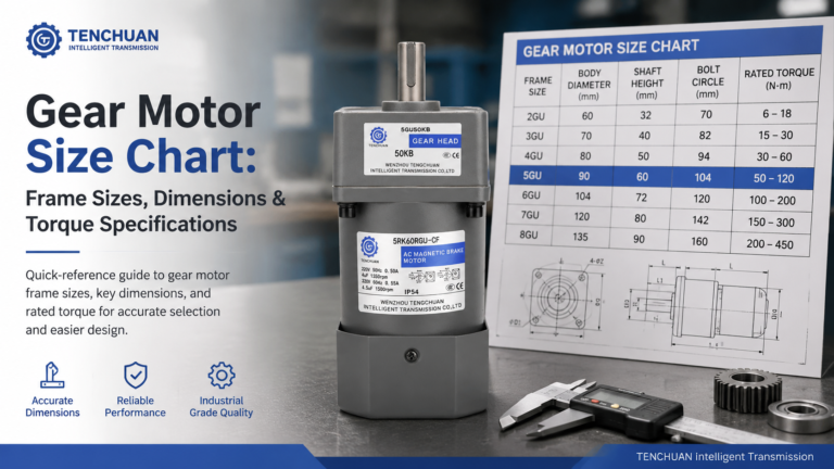
Read a practical gear motor size chart for small AC gear motors. Frame sizes 60-104 mm, dimensions, rated torque and RPM at common ratios, mounting styles.