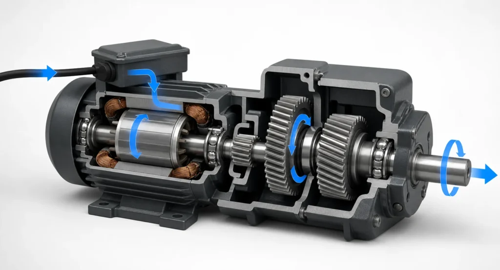
A gear reducer motor works by combining an electric motor with a reduction gearbox. Electrical energy creates high-speed rotation in the motor. A small input gear then drives one or more larger gears, lowering output speed while increasing usable torque. The final output shaft transfers that slower, stronger rotation to a conveyor, feeder, mixer, turntable, or other machine.
The reducer does not create extra power. Instead, it trades speed for torque while losing a small amount of energy to gear friction, bearings, seals, and lubricant movement. Understanding that power path makes it easier to select the right ratio, motor size, voltage, and mounting arrangement. Tenchuan Home page provides an overview of its compact industrial drive products.
The Main Parts Inside a Gear Reducer Motor
Although gearmotor designs vary, most integrated units contain the same functional groups:
Stator: stationary windings or magnetic elements that create a rotating magnetic field.
Rotor: the rotating motor component that converts the magnetic field into shaft motion.
Motor shaft and input pinion: carry high-speed, relatively low-torque rotation into the reducer.
Gear stages: pairs of small driving gears and larger driven gears that establish the reduction ratio.
Bearings: support the motor, intermediate, and output shafts under radial and axial loads.
Output shaft: delivers reduced speed and multiplied torque to the machine.
Housing, seals, and lubricant: maintain alignment, protect the gears, reduce wear, and retain lubrication.
An integrated design keeps the motor pinion and gearbox input accurately aligned. This eliminates a separate coupling between the motor and reducer, reduces installation space, and can simplify machine assembly.
How the Motor Creates Rotation
In a small AC induction gearmotor, alternating current flows through the stator windings and creates a rotating magnetic field. That field induces current in the rotor, producing electromagnetic torque. The rotor follows the rotating field and turns the motor shaft.
The rotor usually runs slightly below the field’s synchronous speed because induction requires slip. Supply frequency, motor pole count, design, and load determine the actual rated speed. This is why a 50Hz and 60Hz version may produce different motor and geared output speeds even when the physical unit looks similar.
A DC gearmotor works differently on the electrical side. A brushed DC motor uses a commutator and brushes, while a brushless motor uses electronic commutation. However, after the motor shaft begins turning, the mechanical reduction principle is essentially the same: the gear train exchanges speed for torque.
How the Gear Reduction Gearbox Changes Speed and Torque
The gear reduction gearbox contains one or more gear pairs. A small driver gear on the input shaft meshes with a larger driven gear. Because the larger gear has more teeth, the input gear must rotate several times to turn it once.
The basic relationship is:
Reduction ratio = input speed / output speed
If the motor runs at 1,500 rpm and the required output is 50 rpm, the nominal ratio is:
1,500 / 50 = 30:1
The input shaft turns about 30 times for one output revolution. In an ideal loss-free reducer, torque would rise by the same factor. Real gearboxes have losses, so a useful estimate is:
Output torque = motor torque × ratio × gearbox efficiency
For example, a motor delivering 0.4 N·m through a 30:1 reducer at 85% efficiency would produce an estimated 10.2 N·m:
0.4 × 30 × 0.85 = 10.2 N·m
This is only a preliminary calculation. The selected gearhead’s rated allowable torque, shaft capacity, thermal limit, duty cycle, and service factor must also be checked.
What Happens from Startup to Steady Operation?
Power reaches the motor windings through the supply and control circuit.
The electromagnetic field accelerates the rotor and motor shaft.
The input pinion drives the first larger gear, reducing speed and increasing torque.
Additional stages repeat the reduction when a higher total ratio is required.
The output shaft accelerates the load until motor torque and load demand reach equilibrium.
During steady operation, the motor supplies enough torque to overcome load resistance and mechanical losses.
Startup is often the most demanding period. Conveyor mass, friction, acceleration, and load inertia can require more torque than steady running. Frequent starts, reversals, or jams also generate additional heat and gear stress, so a motor should not be selected from continuous running torque alone.
Why Multiple Gear Stages Are Used
A single gear pair can provide a moderate ratio, but very large differences in gear size may be impractical. Designers therefore divide a high total ratio across two or more stages. The stage ratios multiply together.
For example, a first stage of 5:1 and a second stage of 6:1 produce a total ratio of 30:1. Multiple stages allow a compact package, but every mesh introduces friction, heat, backlash, noise, and manufacturing tolerances. Higher ratio is therefore not automatically better; it must still deliver the required output speed efficiently.
How Gear Design Changes the Power Path
Gear arrangement
Output layout
Typical characteristics
Common applications
Spur or helical stages
Parallel or offset shaft
Direct, compact transmission; helical teeth can run smoothly
Conveyors, feeders, packaging
Planetary
Inline/coaxial
Load sharing and high torque density
Compact automation, positioning
Worm
Right angle
Large reduction in a compact 90-degree layout; efficiency varies
Gates, turntables, space-limited drives
Bevel or hypoid
Right angle
Directional change with different efficiency and load behavior
Conveyors, mixers, transfer equipment
For compact industrial applications, review the Small AC Gear Reducer Motors category and compare the exact gearhead, ratio, output shaft, and mounting options rather than relying on the product family name alone.
Gear Reduction Motor 110 Volt vs 12V
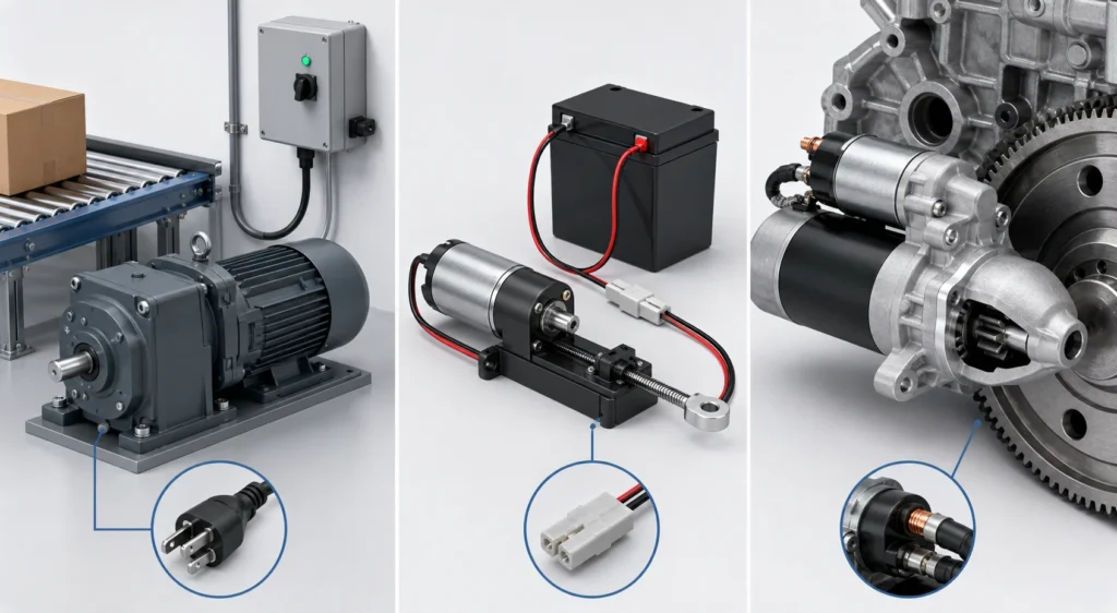
The phrase gear reduction motor 110 volt usually describes an AC gearmotor intended for a nominal 110–120V single-phase supply. It suits grid-powered machinery when its frequency, phase, wiring, capacitor, and control method match the installation. Confirm whether the rating is for 50Hz or 60Hz because frequency affects motor speed.
A gear reduction motor 12V is usually a low-voltage DC gearmotor used in battery-powered equipment, actuators, vehicles, portable mechanisms, or control systems. It needs a power supply and controller capable of providing starting current without excessive voltage drop. A 12V motor is not a direct substitute for a 110V AC unit even if both list similar output rpm.
Is a Gear Reduction Starter the Same Product?
No. A gear reduction starter normally means an automotive or engine starter motor with an internal reduction gear set. Its high-speed DC motor drives a pinion that engages the engine flywheel, producing high cranking torque for a short duty cycle.
An industrial gear reducer motor, by contrast, drives production machinery and may operate continuously or cyclically for many hours. Both devices use the same basic speed-for-torque principle, but their electrical design, duty, output interface, controls, safety requirements, and applications are different.
How Power Rating and Ratio Work Together
Motor wattage describes power capacity, while the ratio determines how that power is delivered as speed and torque. Product comparisons should always use both. A 25W small AC gear reducer motor may suit light feeders and indexing mechanisms. A 60W model can be evaluated for small rollers and conveyors. Packaging transfers may lead to the 120W model, while more demanding compact machinery can be compared with the 200W model.
These examples identify available product classes, not automatic selections. Verify output rpm, allowable torque, duty cycle, service margin, shaft loads, voltage, frequency, phase, mounting, and ambient conditions for the exact configuration.
How to Interpret Motor Reducer HS Code Searches
A search for motor reducer HS code does not have one universal answer. Tariff classification depends on the destination country’s tariff schedule, whether the item is AC or DC, rated output, phase, construction, imported configuration, and whether it is a complete motor with a gearbox or a separate gearbox.
In the United States, customs rulings have stated that motors may remain within heading 8501 even when fitted with gears or gearboxes, but the final subheading depends on the motor’s technical specifications and the complete imported article. Other countries can apply different national subdivisions. Use the current destination-country tariff, prepare the datasheet and product drawings, and confirm the code with a customs broker or request a binding ruling. Do not place an unverified code on shipping documents based only on a web search.
Common Misunderstandings About How Gearmotors Work
The reducer creates power: it changes the speed–torque balance; losses mean output power is lower than input mechanical power.
A higher ratio is always stronger: allowable torque, efficiency, heat, shaft strength, and required speed still impose limits.
Rated torque covers every startup: acceleration, shock, and jams can exceed steady demand.
Lowering voltage is a universal speed-control method: motor type and controller determine safe, usable control.
Every right-angle reducer self-locks: backdrivability must be verified; safety-critical holding requires a rated brake or holding system.
From Electrical Input to Useful Machine Motion
A gear reducer motor turns electrical energy into high-speed rotor motion, passes it through a calculated gear ratio, and delivers lower-speed, higher-torque rotation to the load. Reliable performance depends on matching every stage—from supply and winding to gears, bearings, output shaft, and driven machine.
Explore Tenchuan’s Solutions for application context and visit About Us for manufacturing background. For a project-specific recommendation, send the load, speed, torque, voltage, and installation details through Contact Us.
Frequently Asked Questions
Does a gear reducer motor increase torque?
Yes. It increases output torque approximately in proportion to the reduction ratio, reduced by gearbox losses and limited by the gearhead and shaft ratings.
How do I calculate gear reducer motor output speed?
Divide the motor’s loaded speed by the reduction ratio. Confirm the result against the manufacturer’s rated output speed at the actual voltage and frequency.
Why does a gear reducer motor get hot?
Heat comes from motor winding losses, gear friction, bearings, seals, frequent starts, overload, poor ventilation, and unsuitable low-speed operation. Compare measured temperature with the permitted rating.
Can the output shaft drive a pulley directly?
Only when pulley tension and overhung load remain within the specified radial-load rating. Otherwise support the pulley on external bearings and connect it with a suitable coupling.
What data is needed to select a gear reducer motor?
Provide required output rpm, continuous and peak torque, duty cycle, starts per hour, voltage, phase, frequency, control and brake needs, shaft loads, mounting, environment, and available space.
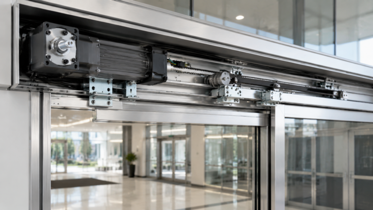
Practical guide to selecting a gear motor for door openers: calculate required torque and output speed, understand self-locking worm gear drives, and match the right AC gear motor to your door type.
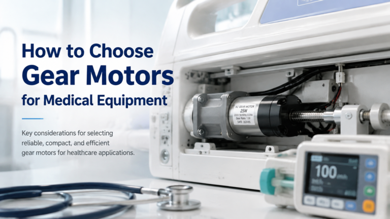
Selection guide for gear motors used in hospital beds, infusion pumps, ventilators, lab equipment and other medical devices. Covers noise, precision, IEC 60601-1 safety, IP rating and self-locking requirements, plus a step-by-step selection workflow and application table.
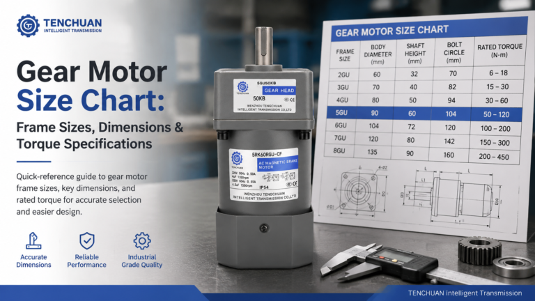
Read a practical gear motor size chart for small AC gear motors. Frame sizes 60-104 mm, dimensions, rated torque and RPM at common ratios, mounting styles.