Parallel-Shaft vs Right-Angle Gear Motor: Which Fits Your Machine
Right-angle vs inline gear motor compared with real allowable load tables: efficiency, torque, the self-locking myth and how to decide in five steps.
Read More
A conveyor gear motor is a deceptively simple specification until the conveyor is inclined, or accumulating, or started twenty times an hour. Then the drive stops being a ratio and a power rating and becomes a set of decisions about slip, holding, heat and mechanical mounting. This guide covers those decisions for belt conveyors, in the order they should be made, with the numbers that make each one concrete.
Before any catalogue is opened, four values should be fixed. They come from the conveyor design, not from the motor, and they determine everything downstream.
| Variable | Typical range | Why it drives the motor choice |
|---|---|---|
| Belt speed | 0.1 – 1.5 m/s for process conveyors | Combined with pulley diameter, it fixes output r/min and therefore the ratio |
| Drive pulley diameter | 80 – 300 mm on light and medium conveyors | Sets the torque arm: a small pulley needs more torque for the same belt pull |
| Total moving mass | Belt + product + any accumulation | Sets the tangential force, and the start-up load if the belt is loaded at rest |
| Starts per hour and duty | 1 – 60 starts/h, 8 – 24 h/day | Decides the service factor, the motor duty class and whether a VFD is warranted |
The conversion from belt speed to shaft speed uses the effective pulley diameter, including lagging:
n = 60 × v ÷ (π × D)
A 0.4 m/s belt on a 125 mm pulley needs about 61 r/min at the drive shaft. The same belt on a 250 mm pulley needs only 31 r/min — half the speed and twice the torque for the same belt pull. This is why pulley diameter is a drive decision, not just a mechanical one.
For a horizontal conveyor the resisting force is dominated by how the belt is supported. A slider bed, where the belt slides on a steel or polymer plate, has a friction coefficient in the region of 0.05–0.10 depending on the belt back and the load. A roller-supported belt is lower, often below 0.05 in good condition. Multiplied across a long conveyor, that difference decides whether a 0.4 kW or a 1.5 kW drive is needed.
For an inclined conveyor, add the gravity term, and note that it works in one direction only:
F = m × g × (sin θ + μ × cos θ)
On a decline the sign of the gravity term reverses, and the conveyor may run away under load. That case does not need a bigger motor; it needs a brake motor or a backstop, and the two are not interchangeable. A backstop prevents reverse rotation mechanically and is the correct choice for inclined conveyors that must hold position when stopped. An electromagnetic brake holds the load and also stops it, but a brake cycled as a production stop will wear out long before the motor does.
Conveyors that accumulate product — a run-on belt feeding an indexing machine, a cooling run that fills up during a downstream stoppage — can present a starting load several times their running load. The drive then has to break away a fully loaded belt, and an AC induction motor’s starting torque, roughly two to two and a half times rated, may not be enough.
Three practical solutions, in order of preference:
Start frequency is the other half of the same problem. A conveyor doing 30 starts an hour is not an S1 continuous duty application in thermal terms, even though the belt never stops for long. Each start injects locked-rotor current and heat into the windings; the motor’s permitted cycle rate depends on its thermal capacity, so a drive chosen purely on running torque can overheat in a high-cycle indexing duty.
| Arrangement | Best for | Watch for |
|---|---|---|
| Foot-mounted gear motor + coupling | Fixed conveyors with room for a baseplate | Alignment and coupling wear; needs a guard |
| Flange-mounted (B5/B14) on the drive shaft end | Compact layouts, retrofits | Flange and shaft must carry the drive’s weight and reaction torque |
| Shaft-mounted reducer with torque arm | Heavy conveyors, no baseplate available | Torque arm must be free to float; alignment-free but needs a backstop on inclines |
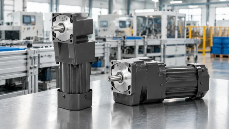
| Direct-coupled right-angle gear motor | Conveyors where the drive must sit alongside the frame | Slightly lower efficiency per stage; check the overhung load on the shaft |
Drive position also matters. Head-end drives put the loaded belt in tension and are the conventional choice; tail-end drives reduce the torque requirement slightly on long belts but expose the drive to more spillage. Either way, the reducer’s overhung load rating becomes critical the moment a pulley or sprocket sits on its output shaft — an over-tensioned belt is a bearing failure waiting to happen, and no amount of motor margin compensates for it.
Fixed-speed conveyors are cheapest with a direct-on-line AC gear motor. A VFD earns its place when any of the following is true: the belt speed must be tuned to a downstream machine; the product requires a soft start to avoid tipping or sliding; the conveyor runs at different speeds for different SKUs; or the drive must reverse. Two specification points follow:
Belt tracking, pulley lagging and take-up travel all interact with drive choice as well: a conveyor that has to be run fast to track properly is usually a take-up or alignment problem, not a drive problem. Wider material-handling drives, including transfers and elevators, are compared in gear motors for material handling.
Conveyors live in dusty, wet or washdown environments far more often than their drives are specified for. Three choices cover most cases: IP55 for general indoor and outdoor conveyor duty with a drip cover, washdown-rated housings with food-grade lubricant where the line is cleaned with water, and sealed cable entries where the motor sits near spillage. Dust is the more common killer than water on bulk conveyors — it packs into cooling fins, and a motor that cannot shed heat derates quietly until it trips.
The arithmetic behind steps 2 to 4 is set out with a full worked example in gear reducer sizing; this article’s job is the conveyor-specific judgement around it. Standard conveyor drives generally land on the medium frames — the 750 W and 1500 W gear motors cover a large share of light and medium belt conveyor duty, with the 400 W frame handling short, light runs.
Conveyor gear motor selection is mostly about the cases the running calculation misses: a fully loaded start, an incline that wants to run backwards, thirty starts an hour, and a pulley that puts bending load on the output shaft. Handle those four explicitly and the ratio and power rating become straightforward. If you can supply belt speed, pulley diameter, load and incline, the medium gear reducer motors can be matched to the duty directly.
Divide 60 times the belt speed in m/s by π times the effective pulley diameter in metres. A 0.5 m/s belt on a 200 mm pulley needs about 48 r/min at the drive shaft.
If the loaded belt would run backwards when the drive stops, yes — a backstop for pure holding, a brake motor if the load must also be stopped. Horizontal conveyors normally need neither.
Because the breakaway torque of a loaded belt exceeds the motor’s starting torque, or the drive was sized on running load only. Check the starting condition first, then the service factor used in the original selection.
Yes, with an inverter-rated motor and a ratio that keeps normal running between roughly 30 and 60 Hz. Add forced cooling if the conveyor runs at very low speed for long periods.
Shaft-mounted units save space and alignment work on heavy conveyors, while foot-mounted units are simpler to service on light ones. The choice usually follows the frame design rather than the drive itself.