Parallel-Shaft vs Right-Angle Gear Motor: Which Fits Your Machine
Right-angle vs inline gear motor compared with real allowable load tables: efficiency, torque, the self-locking myth and how to decide in five steps.
Read More
Choosing a gear motor for material handling means sizing for two different loads that share one machine frame. A horizontal conveyor asks for steady torque at a controlled speed. A lifting or indexing axis asks for a much larger breakaway torque, holds a static load, and may reverse every few seconds. Get the distinction wrong and the drive either stalls under a full belt or runs hot on a duty cycle it was never rated for. This guide works through the sequence for compact right-angle AC gear motors in the 25-300 W class: output speed, running torque, starting torque, service factor, overhung load, then ratio and duty confirmation.
A horizontal belt or roller conveyor is a friction-dominated load. The torque needed to keep it moving is roughly proportional to the weight on the belt, the friction of the rollers or slider bed, and the tension needed to pull the belt around the pulleys. Once the belt moves, demand is fairly flat. The hard part is the first moment: a fully loaded belt that stopped mid-cycle needs considerably more torque to restart than to keep running.
A lifting, hoisting or indexing axis is gravity and inertia dominated. The drive must overcome the weight of the load directly, from rest, on every cycle. Acceleration torque, static friction in the guides and any imbalance in the mechanism all land on the output shaft at once.
That difference is why a gear motor that works well on a conveyor can be badly undersized on a lift of similar wattage — and why nameplate wattage is the least useful number for this decision.
You cannot select from a catalog using the machine’s product name. Five values settle almost every application in this class.
Work backwards from the process. For a belt conveyor, convert belt speed into pulley speed:
Pulley speed (r/min) = Belt speed (m/min) ÷ Pulley circumference (m)
Use the effective working diameter, not the bare metal diameter, when the belt is thick. For a lifting axis, output speed comes from the screw lead or drum diameter and the required travel time. Then divide motor speed by output speed to get the ratio:
Gear ratio = Motor rated speed ÷ Required output speed
Use the rated speed, not the synchronous speed: a four-pole induction motor in this class runs at roughly 1350-1550 r/min under load, and that slip changes the ratio you should order. The gear ratio calculation guide works through the arithmetic with chain and pulley reductions included.
Running torque keeps the load moving at speed: friction on a conveyor, suspended weight on a lift. Compare the result against the gearbox’s allowable output load table rather than the base motor’s rated torque — gearboxes are rated at their output shaft, and that figure is set by the gear train.
Conveyors commonly need substantially more torque to start than to run, particularly when they stop under full load. Breakaway torque overcomes static friction before anything moves; after that, demand drops to the steady running level. Design around the starting case.
A service factor is a multiplier on the calculated torque covering shock, duty severity and the cost of being wrong. A uniform load on an eight-hour shift sits at the low end; intermittent shock, frequent reversing or near-continuous operation push it up. Under-sizing a gearbox to save on purchase price is a poor trade, because the gear train is the part that fails — and it fails as downtime.
This is the number most projects skip, and the one that quietly destroys bearings. When a sprocket, pulley or chain wheel is mounted on the gearbox output shaft, the chain pull acts as a sideways force at a distance from the bearing. That is an overhung load: a radial force, separate from transmitted torque, with its own limit. A drive with plenty of torque margin can still fail early because the chain pulls too hard on too long a shaft overhang. Keep the sprocket close to the gearbox, support the outboard end, and check the radial rating before ordering. Torque arms and output flanges exist to take that reaction force off the housing; the gear motor accessories guide covers how this is handled in practice.
| Number | Where it comes from | What it decides |
|---|---|---|
| Output speed (r/min) | Belt speed ÷ pulley circumference, or travel time ÷ lead | The gear ratio, and whether that ratio exists in the catalog |
| Running torque (N·m) | Friction or suspended weight at the driven shaft | Whether the allowable load table is large enough |
| Starting torque (N·m) | Breakaway friction plus acceleration, from rest | Frame size and motor variant selection |
| Service factor | Load uniformity, starts per hour, shift length | The margin between calculated torque and allowable load |
| Overhung load (N) | Chain or belt pull × distance from bearing | Shaft support, mounting method, bearing life |
Most mechanisms in this power class fall into a few recognizable speed bands. Treat these as starting points for the ratio search — the process speed always wins.
| Mechanism | Typical output speed | Sizing emphasis |
|---|---|---|
| Belt conveyor, general transfer | 30-90 r/min | Starting torque under full load; belt tension |
| Roller or chain conveyor | 20-60 r/min | Overhung load on the sprocket; chain pull |
| Inclined conveyor | 15-50 r/min | Gravity component; back-driving behaviour |
| Lifting screw or small hoist | 5-30 r/min | Breakaway torque from rest; holding method |
| Indexing and transfer table | 10-40 r/min | Acceleration torque; starts per hour |

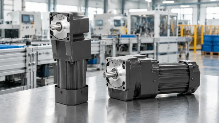
Right-angle drives turn the output 90 degrees from the motor axis, so the motor body sits alongside the frame instead of projecting into the aisle — often the difference between fitting and not fitting. It is the most common choice for compact material handling stations, and the reason a 120 W to 300 W right-angle AC gear motor suits medium-duty conveyor and lifting axes.
Inline drives keep motor and output on one axis and are more efficient where there is room for the unit’s full length — typically 5–10 percentage points better than a right-angle stage of the same ratio, which shows up as less heat in the housing.
Everything above is about the 25–300 W class. Once the drive passes roughly 300 W, three things change at once, and they change the selection method:
That range is covered by the medium gear reducer motor series: 400 W, 750 W, 1.5 kW, 2.2 kW and 3.7 kW in vertical and horizontal builds. Above 3.7 kW you have left this product class and are into separate motor-and-reducer assemblies with oil lubrication.
The 6RK series right-angle AC gear motor uses a 100 mm frame with a 90-degree output, available in single-phase 110 V and 220 V and three-phase 380 V versions. The base motor runs at 1350-1550 r/min with rated torque in the 740-1840 mN·m band. Output power spans 120 W to 250 W, and ratios run from 3:1 to 500:1, putting usable output speed from roughly 3 r/min up to about 500 r/min.
What matters for material handling is the allowable output load, listed per power rating and per ratio and growing as the ratio deepens: a 120 W unit reaches about 31 N·m at the deeper end of its range, while larger frames reach up to roughly 43 N·m (440 kg·cm). The motor variant matters too — the catalog lists a reversible 30-minute duty version and a continuous-duty version, and a 30-minute reversible unit is not a continuous-duty drive. Cross-checking frame and shaft data against the gear motor size chart before fixing a layout saves rework.
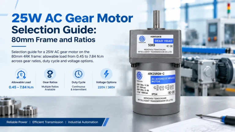
For lighter stations — small diverter pushers, light transfer rollers, low-load indexing — a 40 W to 140 W right-angle gear motor covers the same 90-degree mounting logic at a smaller frame. For the lightest axes, such as a small flap or positioning roller, a 25 W right-angle gear motor is usually sufficient.
The first is duty cycle: thermal rating depends on how long the drive runs, how often it starts and how hard it works. A reversible unit listed at 30-minute duty can run all day if the actual duty is intermittent and the load sits well inside the rating, but it cannot run continuously at rated torque.
The second is holding. A gear motor is a drive, not a brake. It can resist back-driving through friction and gear geometry, and a worm arrangement does so more convincingly than spur or helical, but none of that is a certified holding function. Any axis where a released load would fall or drift needs an independent brake, a self-locking screw or a mechanical stop.

| Mistake | What it looks like in service | Better approach |
|---|---|---|
| Sizing on motor wattage alone | Drive stalls on a loaded start | Size on output torque, then confirm with power |
| Ignoring overhung load | Premature bearing noise and failure | Check the radial rating; support the shaft outboard |
| Using running torque as the design case | Occasional refusal to restart under load | Design around breakaway and acceleration torque |
| Treating a 30-minute reversible rating as continuous | Motor overheating and winding failure | Match the variant to the real duty pattern |
| Relying on the gearbox to hold a suspended load | Load drifts or falls when power is cut | Add a brake, self-locking screw or mechanical stop |
| Choosing a ratio without checking process speed | Throughput wrong; no adjustment left | Calculate output speed first, then find the ratio |
Material handling drive selection comes down to sequence. Decide whether the load is friction-dominated or gravity-dominated, convert the process requirement into an output speed, calculate running and starting torque, apply a service factor, then check the overhung load on the output shaft. Only after those five steps does the choice between a right-angle, inline or worm arrangement — and between a 25 W, 120 W or 250 W frame — become straightforward rather than a guess. Confirm duty cycle and holding method last, because those two decide whether a correctly sized drive survives its first month in service.
If you are sizing a conveyor, lifting axis or transfer station and want the allowable load figures matched against your actual numbers, send the speed, load and mounting layout and the drive can be specified against the catalog.
Convert belt speed into pulley speed using pulley circumference, then divide motor rated speed by that figure to get the ratio. Calculate the torque needed at the driven shaft, apply a service factor, and confirm the result sits inside the gearbox’s allowable output load table for that ratio.
Static friction is higher than sliding friction, and a belt stopped under full load also has to accelerate the material and belt mass. Breakaway and acceleration torque at start-up can therefore be substantially higher than steady running torque.
It is the radial force a sprocket, pulley or chain wheel applies to the output shaft at a distance from the bearing. Exceeding it overloads the output bearing even when the torque rating looks comfortable.
It can resist back-driving through friction and gear geometry, but this is not a certified holding function. Any axis where a released load would fall or drift needs an independent brake or mechanical stop.
Right-angle drives are usually better where installation space is tight, because the motor body sits alongside the frame instead of projecting along the axis. Inline drives are more efficient when there is room for the unit’s full length.
Most small transfer and roller conveyors in this class run between roughly 20 and 90 r/min at the drive shaft. Calculate the exact figure from process speed rather than picking a number from a table.