Parallel-Shaft vs Right-Angle Gear Motor: Which Fits Your Machine
Right-angle vs inline gear motor compared with real allowable load tables: efficiency, torque, the self-locking myth and how to decide in five steps.
Read More
Most AC gear motor problems that reach a supplier’s inbox are not mechanical. The gearbox is fine, the ratio is right, the frame bolts up — and the machine still stalls, overheats, or runs 20% faster than the drawing said it would. The cause is usually electrical: the wrong phase type, a frequency that was never checked, or a supply voltage that sags under load. This guide covers the electrical half of an AC gear motor specification, in the order that decides success on the shop floor.
Three decisions fix 90% of AC gear motor selection, and they must be made in order. Phase type decides what torque is available at standstill. Frequency decides what speed the gearbox actually sees. Voltage decides whether the motor can hold its rated torque without overheating. Get the first two wrong and no gear ratio can rescue the application.
| Decision | What it controls | Get it wrong and you see |
|---|---|---|
| Single-phase or three-phase | Starting torque, current draw, frame cost, maximum practical power | Motor hums or crawls at start under load; tripped breakers; oversized wiring |
| 50 Hz or 60 Hz (or dual-rated) | Output speed of the whole gearmotor, and therefore machine cycle rate | Conveyor or machine runs 20% fast or slow; cycle timing drifts out of spec |
| Supply voltage and tolerance | Available torque, winding temperature rise, insulation life | Overheating, nuisance overload trips, short motor life on long cable runs |
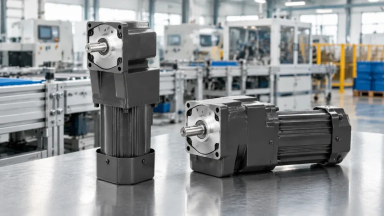
An AC gear motor is an AC induction motor bolted to a reduction gearbox and sold as one assembly. The motor runs at a fixed speed determined by pole count and supply frequency; the gearbox multiplies torque and divides speed. Because the pair is matched at the factory, the allowable output torque table on the datasheet already accounts for the motor’s thermal capacity and the gearbox’s mechanical rating — which is why you should read the gearmotor’s output table rather than the motor’s nameplate power alone. If you are still clarifying the basic vocabulary, what a gear motor is and how the two halves interact is a useful starting point.
For a three-phase motor the relationship between power, speed and torque is fixed:
T = 9550 × P ÷ n
where T is torque in N·m, P is motor power in kW and n is output speed in r/min. Note that this is the torque the motor delivers at its own shaft, before the gearbox. A 0.75 kW four-pole motor turning at 1450 r/min produces about 4.9 N·m; run it through a 1:100 reducer and the output shaft is rated near 490 N·m minus gear losses. The motor never changed — only the ratio did.
A three-phase induction motor produces a rotating magnetic field by itself, so it develops roughly two to two and a half times its full-load torque at standstill. A single-phase motor cannot do that without help, because one winding produces a pulsating field rather than a rotating one. Single-phase gear motors solve this in one of three ways, and the choice changes how the drive behaves on a loaded machine:
This is why the same 120 W gear motor can be perfectly adequate on one machine and hopeless on another. If the load must break away from rest — an inclined conveyor, a gate, a mixer with settled product — check the published starting torque, not just the running torque.
Single-phase gear motors are practical up to roughly 2.2 kW. Above that, three-phase is cheaper per kilowatt, smaller per kilowatt, and more efficient, because single-phase designs need larger frames and heavier capacitors for the same output. If your machine will ever be built in volume for a market with three-phase supply, specify three-phase from the prototype onward — re-engineering the electrical side after tooling is fixed is expensive.
Three-phase motors reverse by swapping any two phases and are protected by a thermal overload relay or a motor protection circuit breaker. Single-phase capacitor motors reverse by swapping the auxiliary winding connections at the terminal box, and they often rely on the motor’s own thermal protector. If the machine needs frequent reversing — packaging indexers, damper actuators, sliding gates — three-phase with a reversing contactor is the cleaner route. For speed control, three-phase plus a VFD is standard; single-phase speed control needs a dedicated speed controller and a motor designed for it, which is why HVAC damper and fan drives often specify three-phase as soon as modulation is required.
Synchronous speed depends on frequency and pole count only. A four-pole motor turns at 1500 r/min synchronous at 50 Hz and 1800 r/min at 60 Hz, with rated speeds typically around 1450 and 1750 r/min after slip. The gearbox ratio does not change, so the whole gearmotor’s output speed scales with frequency:
| Motor / ratio | Output at 50 Hz | Output at 60 Hz | Practical effect |
|---|---|---|---|
| 4-pole, 1:10 | ≈145 r/min | ≈175 r/min | Machine runs ~20% faster; cycle times shorten |
| 4-pole, 1:50 | ≈29 r/min | ≈35 r/min | Conveyor belt speed rises proportionally |
| 4-pole, 1:180 | ≈8 r/min | ≈10 r/min | Slow, high-torque duty; torque margin shrinks slightly |
| 6-pole, 1:50 | ≈18 r/min | ≈23 r/min | Alternative when 50 Hz speed is already too fast |
Speed is the visible change. The invisible one is flux. A motor wound for 400 V at 50 Hz has a voltage-to-frequency ratio of 8 V/Hz; run the same motor at 60 Hz on the same 400 V and the ratio falls to 6.7 V/Hz. Flux drops with it, and because torque scales roughly with flux squared, available torque falls by close to a third while power drops by around a fifth. So a motor run “a bit faster” on a 60 Hz grid is not simply a faster version of itself — it is a weaker one.
Motor torque is proportional to the square of the applied voltage. A 10% voltage drop costs roughly 19% of available torque and measurably increases current and winding temperature at the same load. In practice this shows up on long cable runs, on shared feeders with welding equipment, and in regions where nominal voltage is 380 V but measured voltage sits at 360 V at the end of the day. Three points follow:
Class F insulation is common on industrial gear motors and gives thermal headroom above the class B temperature rise actually used in most designs; that headroom is what allows a motor to survive a hot afternoon in a non-air-conditioned plant. Duty designation matters just as much. S1 continuous means the motor is rated to run at load indefinitely, while S2 and S3 indicate short-time or intermittent duty — a gear motor sold for S3 indexing work is not a drop-in replacement for an S1 conveyor drive.
Enclosure protection is often decided by the washdown schedule as much as by dust. IP54 covers most indoor machinery; IP55 handles washdown splash and outdoor installation with a drip cover. Food and beverage lines may need a washdown-rated unit with a smooth housing and food-grade lubricant, as covered in this guide to food-grade gear motor selection. Where the machine must hold position when power is removed — hoists, gate operators, incline conveyors — specify an electromagnetic brake, and remember that the brake is a holding device, not a service brake for stopping a moving load repeatedly.
AC induction gear motors hold speed well and need no controller for fixed-speed duty, which is why they dominate conveyors, mixers, door operators and packaging machinery. They are the wrong answer when the machine needs controlled acceleration, precise stopping position, or a very wide speed range with constant torque — that is VFD territory, or a servo system if indexing accuracy is the requirement. They are also the wrong answer for battery-powered or low-voltage portable equipment, where DC gear motors win on efficiency and voltage flexibility; the trade-offs are set out in geared DC motor vs geared AC motor.
Specify an AC gear motor by deciding phase, then frequency, then voltage, then mechanical duty — and confirm the output torque at the actual running speed rather than at the motor’s nameplate rating. A gear motor whose electrical specification matches the real supply will run cool, hold its speed, and outlast three units chosen on wattage alone. If you have the supply details, the required output speed and the load torque, the AC gear motor range can be matched to the application directly.
Usually yes, and it will turn about 20% faster. But torque and power fall because the voltage-to-frequency ratio drops, so a motor that was already close to its torque limit may stall or overheat. Confirm with the manufacturer or fit a motor wound for 60 Hz.
For the same frame and power rating, three-phase motors produce more starting torque, run more efficiently and cost less per kilowatt. A capacitor-start single-phase design can still start a loaded machine, but a permanent split capacitor design usually cannot.
Nameplate speed is a rated speed at rated load, not a no-load speed, and it already includes slip. If the output is slower than the gear ratio predicts, check supply voltage first, then whether the load is exceeding the allowable output torque.
No. Reducing voltage on an induction motor reduces torque and increases heating rather than controlling speed. Use a VFD on three-phase motors, or a matched speed controller with a controller-rated single-phase motor.
A spring-applied electromagnetic brake will hold a static load and stop a moving load a limited number of times per hour. For frequent dynamic braking, or for loads that must not creep, size the brake torque and cycle rate with the supplier rather than assuming the brake is rated for the duty.