Parallel-Shaft vs Right-Angle Gear Motor: Which Fits Your Machine
Right-angle vs inline gear motor compared with real allowable load tables: efficiency, torque, the self-locking myth and how to decide in five steps.
Read More
Selecting a gear motor for pump duty is not the same exercise as picking a drive for a conveyor. A pump presents a load that shifts with fluid viscosity, temperature and discharge pressure, and it punishes a motor sized on wattage alone. This guide covers the practical sequence: work out the torque the pump shaft demands, add margin for cold starts and wear, then choose the gear ratio, duty cycle and mounting arrangement that fit the machine.
Scope note. This guide covers the pump duties a compact AC gear motor actually serves: metering and dosing pumps, small progressive-cavity and screw pumps, lubricant and chemical transfer, and slow-turning positive-displacement pumps that need 5–120 r/min at high shaft torque. If the pump is a centrifugal unit running near its best-efficiency point at 1,450 or 2,900 r/min, it should be direct-coupled to a motor — gearing it down adds cost, losses and a failure point for no benefit.
Most pump sizing mistakes trace back to one habit: choosing a motor by output power in watts because that is the number on the label. Power describes how fast work is done; torque describes whether the shaft can turn the load at all. A 250 W AC motor at its rated 1350 r/min delivers ample power but almost no torque at 30 r/min. Run the same motor through a 500:1 gearbox and the output becomes slow, strong and stable — the motor did not change, the gear ratio did the work. So size torque first, speed second, power third. Power then confirms the choice and sets the thermal expectation, because a motor running near its torque limit runs hot even when the wattage looks comfortable.
You cannot size a pump drive from the pump’s model name. Four values decide everything, and all four come from the pump datasheet, the system design or a simple calculation.
Displacement is the volume a positive-displacement pump moves per shaft revolution, usually in millilitres or cubic centimetres. Required flow divided by displacement gives the shaft speed you need: a pump displacing 4 mL per revolution delivering 120 mL per minute needs 30 revolutions per minute. That single division eliminates most available ratios immediately.
Differential pressure is the pressure the pump must generate across itself, not the gauge reading at the outlet. It includes discharge pressure, suction pressure and losses from pipework, filters, valves and elevation. A pump lifting fluid through a partly blocked strainer sees more differential pressure than the same pump on a clean line, and the drive feels the difference as extra torque.
Some duties tolerate a wide speed band; reagent dosing and lubricant metering hold flow accuracy only inside a narrow window. Note the acceptable minimum and maximum shaft speed before reading ratio tables, because a ratio that works on paper may leave no room for adjustment later.
With displacement and differential pressure known, continuous torque demand follows a standard relationship for positive-displacement pumps:
T = (Δp × V) ÷ (2π × η)
where T is torque, Δp is differential pressure, V is displacement per revolution and η is the combined mechanical efficiency of pump and drive. Treat the result as a baseline for a warm, thin fluid at the rated operating point — a screening figure, not a guarantee — and compare it against the gear motor’s allowable load table rather than its motor-only rating.
| Value | Where to find it | Why it changes the drive choice |
|---|---|---|
| Displacement (mL/rev) | Pump datasheet or pump geometry | Sets required shaft speed and scales torque demand directly |
| Differential pressure (bar) | Discharge and suction readings plus line losses | Drives torque linearly; rises as filters load up |
| Shaft speed (r/min) | Flow requirement ÷ displacement | Selects the gear ratio and the output speed band |
| Continuous torque (N·m) | Calculated from the formula above | Must sit inside the gear motor’s allowable load table |
Viscosity is the largest variable in pump drive sizing. A fluid that pours easily at 40 °C can be several times thicker at start-up on a cold morning, and a positive-displacement pump pushing thick fluid demands proportionally more torque. Cold, viscous, stalled-fluid conditions can require three to six times the warm running torque — momentary, but enough to stall or trip a drive with no starting margin.
Apply a working margin on the calculated continuous torque: roughly 1.2 to 1.3 times for steady process duty with temperature control, and 1.3 to 1.5 times or more for intermittent duty, unheated fluids or outdoor installations. Then confirm the motor’s starting capability clears the cold-start estimate, not just the running figure.
With torque demand and target shaft speed known, ratio selection becomes a shortlist exercise. Output speed is motor speed divided by the gear ratio, so a 1350 r/min motor behind a 25:1 gearbox turns the pump shaft at roughly 54 r/min.
| Gear ratio | Approx. output speed at 1350 r/min | Typical pump duty |
|---|---|---|
| 3:1 to 10:1 | 135 to 450 r/min | High-flow transfer and circulation where speed matters more than torque |
| 12.5:1 to 25:1 | 54 to 108 r/min | General process transfer, gear pump drives, coolant circulation |
| 30:1 to 60:1 | 22 to 45 r/min | Metering, dosing and lubricant delivery at controlled flow |
| 75:1 to 500:1 | 2.7 to 18 r/min | Slow positive-displacement pumping, viscous media, precise dosing |
Two cautions apply at the extremes. At high ratios the real output speed may drift from the theoretical figure as load changes, so leave headroom in the flow tolerance. At low ratios the gear motor may not develop enough torque to start the pump against a cold, pressurised line. A gear motor size chart lets you cross-check frame size, output speed and allowable torque before committing to a ratio.
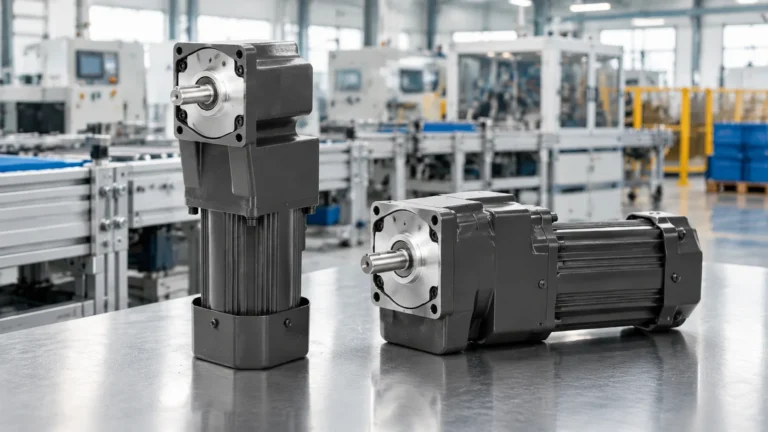
Right-angle gear motors suit pump installations well, because the 90-degree output lets the motor body sit parallel to the pump shaft instead of extending along it — often the difference between fitting and not fitting on a compact skid, a wall-mounted dosing panel or a packaged pump set.
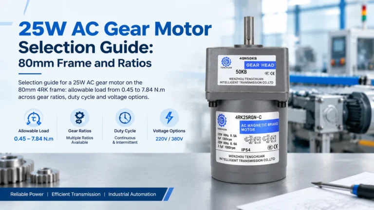
For heavier duties in the 120 W to 300 W class, the 6GU AC right-angle gear reducer motor is the highest-capacity unit in the right-angle range: a 6RK series AC motor on a 100 mm frame with a heavy-duty 90-degree gearbox, rated torque 740 to 1840 mN·m at 1350 to 1550 r/min, ratios from 3:1 to 500:1 and a maximum allowable load up to 43 N·m (440 kg·cm). Single-phase 110 V and 220 V versions sit alongside a three-phase 380 V option, and reversible models carry a 30-minute rating in each direction — so continuous pumping needs a drive specified for that service. Mid-range duties between 40 W and 140 W are served by the 5GU AC right-angle gear reducer motor in a smaller envelope, and where a pump needs only light, intermittent actuation the 4GN AC right-angle gear reducer motor at 25 W keeps the package compact without over-specifying the drive.
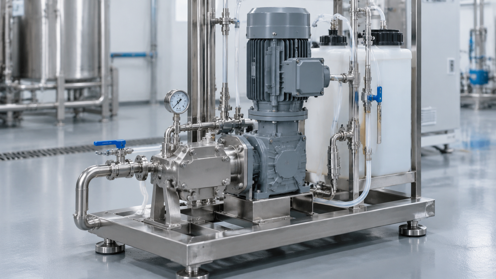
A pump drive fails on the mechanical interface as often as it fails electrically. Three details matter.
Torque arms, flanges and couplings are usually specified separately, so budget for them with the motor. A gear motor accessories guide is a useful checklist when assembling a complete drive package.

A gear motor is a weak fit when flow must be modulated continuously and precisely, when the duty needs very high power at high speed, or when the pump runs constantly at its torque ceiling in a hot, poorly ventilated enclosure. In those cases a variable-speed drive or a larger industrial gearbox class is the better answer.
Sizing a gear motor for a pump comes down to a disciplined order of operations: find the displacement and differential pressure, calculate continuous torque, add margin for cold starts and viscosity, then choose the ratio that lands output speed inside your flow tolerance. Confirm the result against the allowable load table, check the duty rating honestly, and protect the gearbox where the load can lock up.
If you would rather not work through the numbers alone, a broader walkthrough is available in this practical gear motor selection guide, and the engineering team can match a right-angle drive to your pump curve, fluid and mounting layout on request.
Size from torque, not power. Calculate continuous torque from displacement and differential pressure, multiply by 1.2 to 1.5 for viscosity and duty, then pick the smallest gear motor whose allowable load table covers that figure at your required output speed.
Yes. Output speed equals motor speed divided by the gear ratio, so a reduction gearbox is the simplest way to run a pump at 20 to 100 r/min while gaining torque. It is a fixed reduction, so flow cannot be trimmed without changing ratios or adding speed control.
Size against the coldest, thickest condition the pump will see, not the normal running temperature. Cold viscous fluid can demand three to six times the warm torque, so verify the motor’s starting capability against that peak.
It is better whenever space is tight. The 90-degree output lets the motor sit parallel to the pump shaft, shortening the drive package on skids and panels. Performance matches an inline unit with the same ratio and torque rating.
Some high-ratio gearboxes resist back-driving, but a standard gear motor is not a certified holding or braking device. If the pump must stay locked against pressure when power is removed, specify a brake or a separate non-return arrangement.
Load torque rises until it exceeds the gear motor’s maximum allowable figure, and the gearbox can be damaged in a locked-rotor condition. Fit a torque-limiting device or slip coupling to keep the drive inside its rating.