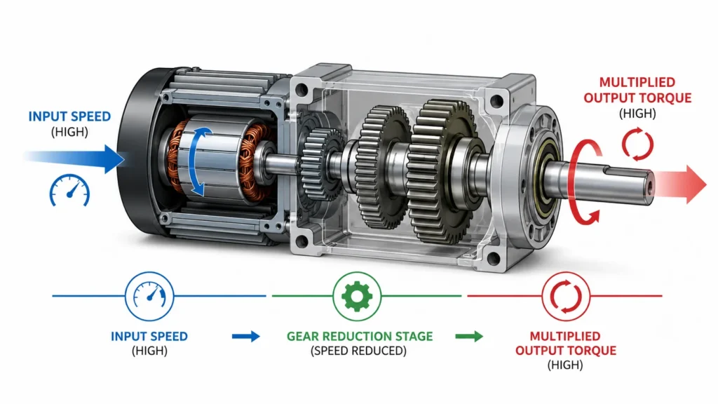
A gear reduction motor combines an electric motor with a gearbox that reduces output speed while multiplying torque. Rather than sending high-speed, low-force rotation directly to a load, the integrated gear train converts that energy into slower, stronger motion. This fundamental principle makes gear reduction motors indispensable across manufacturing, automation, material handling, and packaging equipment.
Whether you are designing a new machine or replacing a failed drive component, understanding the purposes of a gear reduction motor helps you recognize where it adds value and why a standard motor alone often cannot do the job.
Purpose 1: Torque Multiplication
The single most important purpose of a gear reduction motor is torque multiplication. Standard AC induction motors typically operate efficiently at 1,200 to 1,800 RPM — speeds that produce relatively low twisting force. When you need to move a heavy conveyor belt, raise a lift platform, or turn a mixing paddle through thick material, you need far more torque than the motor can deliver on its own.
How Gear Reduction Multiplies Torque
Inside the gearbox, a small drive gear meshes with a larger driven gear. Each time the input shaft turns, the output shaft rotates only a fraction of a revolution. This reduction in speed is proportionally converted into greater output torque. The relationship follows a simple rule:
Reduction Ratio = Input Speed / Output Speed
Output Torque = Input Torque x Reduction Ratio (minus minor efficiency losses)
For example, a motor running at 1,750 RPM paired with a 25:1 gear reduction produces an output speed of 70 RPM — and roughly 25 times the usable torque. This torque multiplication enables relatively compact motors to drive heavy industrial loads without requiring oversized, energy-hungry direct-drive motors.
Real-World Example: Conveyor Systems
In a conveyor application, a 200W small AC gear reducer motor delivering 70 RPM at the drive pulley generates enough torque to move hundreds of kilograms of product along a production line. Without the gear reduction stage, a much larger and more expensive motor would be required — and it would still struggle to produce smooth, controlled movement at low speed.
Purpose 2: Speed Reduction to Match Application Requirements
Most industrial equipment operates at speeds far below a motor’s natural high-RPM range. Conveyor belts might need 30 to 80 RPM at the head pulley. Packaging machines typically run between 50 and 200 RPM. Agitators, screw feeders, and rotary tables each demand specific output speeds that rarely align with a motor’s nameplate RPM.
A gear reduction motor solves this mismatch. By selecting the correct gear ratio, you bring the output speed down to exactly what the equipment needs — without variable frequency drives, belt-pulley reduction, or complex mechanical linkages.
Connecting a motor directly to a load that needs slow, controlled motion creates several problems:
Insufficient torque at low RPM may stall the motor or cause it to draw excessive current.
Poor speed regulation — small fluctuations in motor RPM translate to large variations at the load.
Overheating risk — motors running far below their rated speed lose cooling efficiency and can burn out.
A gear reduction motor eliminates these issues by operating the motor at its efficient rated speed while the gearbox handles the speed conversion.
Common Speed Reduction Ratios
Depending on application needs, gear reduction motors offer a wide range of ratios:
Reduction Ratio
Output Speed (from 1,750 RPM motor)
Typical Application
3:1
~583 RPM
Low-speed fans, light-duty mixers
10:1
~175 RPM
Small conveyors, rotary tables
25:1
~70 RPM
Standard conveyors, gate drives
60:1
~29 RPM
Heavy mixers, lifts, screw feeders
100:1 and above
Below 18 RPM
Heavy-duty hoists, positioning systems
Purpose 3: Motor Protection Through Inertia Matching
Heavy equipment and rotating loads carry significant inertia — they resist starting and, once moving, resist stopping. When a motor couples directly to a high-inertia load, the reflected inertia pushes back through the shaft, causing excessive current draw on startup and potential overshoot during braking.
A gear reduction motor acts as a mechanical buffer. The gearbox separates the motor from the load’s inertia, allowing the motor to accelerate to its operating speed quickly regardless of how massive the driven equipment is. This technique, known as inertia matching, protects the motor from:
Startup current spikes that can trip circuit breakers
Overheating from prolonged acceleration periods
Mechanical shock transferred back from sudden load changes
Premature winding failure from repeated high-stress starts
For applications with frequent starts and stops — such as indexing conveyors, robotic pick-and-place units, or automated gates — proper inertia matching through gear reduction significantly extends motor life.
Purpose 4: Space and Cost Efficiency
A gear reduction motor achieves what would otherwise require a substantially larger motor. Consider a machine that demands 50 Nm of torque at 60 RPM. A direct-drive motor sized to deliver that torque at such low speed would be physically large, heavy, and expensive.
By pairing a compact motor with a reduction gearbox, you get the same output torque in a fraction of the space and at lower cost. A 120W small AC gear reducer motor with a 30:1 ratio, for example, can deliver torque comparable to a much larger direct-drive motor rated at several horsepower — while fitting into a machine enclosure where a large motor simply would not fit.
This space and cost advantage is especially important in:
Automated packaging lines with tightly packed machinery
Robotic systems where every kilogram and cubic centimeter matters
OEM equipment shipped in standardized containers or frames
Purpose 5: Directional Flexibility and Compact Installation
Gear reduction motors offer several shaft orientation options, allowing designers to route power efficiently within the available machine footprint:
Gearbox Configuration
Shaft Orientation
Best For
Parallel shaft (helical/spur)
Input and output parallel
Inline drives, standard conveyors
Right-angle (worm/bevel)
Output at 90 degrees to input
Tight spaces, vertical installations
Coaxial (planetary)
Input and output on same axis
Robotics, precision positioning
Hollow shaft / shaft-mount
Slips directly onto driven shaft
Conveyor head pulleys, compact drives
For example, a right-angle gear reducer motor allows the motor body to sit alongside the equipment rather than protruding outward — a critical advantage when designing packaging machines or food processing lines with tight clearance requirements.
Purpose 6: Smooth Operation and Precise Speed Control
Modern gear reduction motors, particularly those using helical or planetary gearing, deliver smooth power transmission with minimal vibration. This matters in applications where speed consistency directly affects product quality:
In food processing, inconsistent conveyor speed can cause uneven cooking, filling errors, or packaging misalignment.
In printing and labeling equipment, speed variations distort print registration and label placement.
In automated assembly, precise speed control ensures consistent cycle times and accurate part placement.
When combined with a variable frequency drive, a gear reduction motor offers adjustable output speed while maintaining high torque — giving operators fine control over production parameters without sacrificing power.
Industry Applications for Gear Reduction Motors
The purposes of a gear reduction motor map directly to real-world needs across multiple industries. Here is how different sectors leverage these functions:
Conveyor and Material Handling: Torque multiplication for moving heavy loads; speed reduction for controlled material flow. Gear reduction motors drive belt conveyors, roller conveyors, bucket elevators, and screw conveyors throughout warehouses, distribution centers, and production lines.
Packaging Machinery: Precise speed control for filling, sealing, labeling, and cartoning operations. Compact right-angle configurations fit within tight machine frames. Explore our industrial drive solutions for packaging equipment.
Food Processing Equipment: Smooth, reliable operation for mixers, agitators, slicers, and conveyorized ovens. Gear reduction motors withstand frequent washdown cycles when properly sealed.
Automation and Robotics: Planetary gear reduction motors provide high torque density, low backlash, and coaxial design — essential for robotic joints, positioning stages, and pick-and-place mechanisms.
Gate and Barrier Systems: Self-locking worm gear reduction motors hold gates and barriers in position without requiring external brakes, combining safety and energy efficiency.
Gear Reduction Motor Purposes at a Glance
Purpose
What It Achieves
Why It Matters
Torque multiplication
Converts high-speed, low-force rotation into low-speed, high-force output
Enables compact motors to drive heavy loads
Speed reduction
Matches motor output RPM to equipment requirements
Avoids overspeed, stalling, and motor overheating
Inertia matching
Isolates the motor from reflected load inertia
Protects motor windings and extends service life
Space and cost efficiency
Delivers high torque from a compact assembly
Reduces machine footprint and component cost
Directional flexibility
Routes power at parallel, right-angle, or coaxial orientations
Solves tight-fit installation challenges
Smooth speed control
Provides stable, adjustable output speed
Improves product quality and process consistency
When Should You Use a Gear Reduction Motor?
Not every application needs a gear reduction motor. Use the following comparison to determine whether a gear reduction motor suits your requirements:
Scenario
Direct-Drive Motor
Gear Reduction Motor
High-speed fan or pump (1,000+ RPM)
Suitable — no speed reduction needed
Unnecessary — adds cost and complexity
Conveyor running at 50 RPM under load
Poor choice — motor oversized, inefficient
Ideal — compact motor with gearbox delivers required torque at correct speed
Heavy mixer starting under load
Will struggle — high startup current, risk of burnout
Recommended — gearbox handles startup inertia, motor runs at efficient RPM
Robotic arm joint requiring precision
Unsuitable — lacks low-speed torque and positioning accuracy
Excellent — planetary gear reducer provides high torque density and low backlash
Compact machine with space constraints
Large motor may not fit
Small motor + right-angle or coaxial reducer fits tight enclosures
Application with variable speed needs
Requires VFD investment
Pair a fixed-ratio reducer with a VFD for adjustable, high-torque speed control
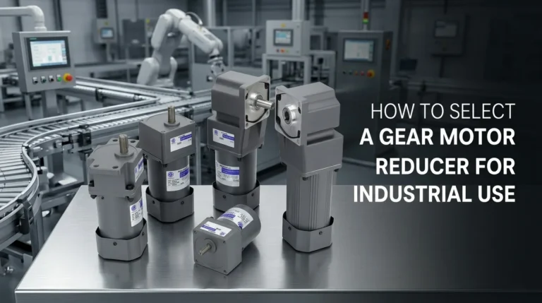
For a more detailed evaluation of your specific requirements, see our complete guide to selecting a gear motor reducer, which covers torque calculations, service factors, and mounting considerations.
Frequently Asked Questions
What is the difference between a gear reduction motor and a regular motor?
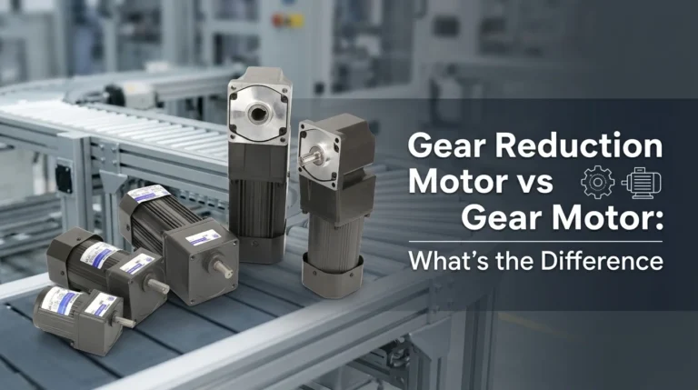
A regular (standard) electric motor runs at a fixed high RPM and delivers relatively low torque. A gear reduction motor integrates a gearbox that reduces the output speed and proportionally increases the output torque. The key difference is that a gear reduction motor delivers low-speed, high-torque output ready for direct coupling to equipment, while a standard motor requires external reduction — through belts, pulleys, or a separate gearbox — to achieve the same result. For a deeper comparison, read our article on gear reduction motor vs gear motor differences.
Can a gear reduction motor run in reverse?
Most gear reduction motors can run in reverse when the motor’s direction is electrically switched — for example, by swapping two phases on a three-phase motor or using a reversing contactor. However, worm gear reduction motors often have self-locking properties that resist back-driving; always check the gearbox type before relying on reversible operation.
What gear ratio do I need for my application?
The required gear ratio depends on your motor’s input speed and your equipment’s target output speed. Use the formula: Ratio = Motor Input RPM / Desired Output RPM. For example, a 1,750 RPM motor driving a conveyor at 70 RPM needs a 25:1 ratio. Also verify that the motor’s torque, multiplied by the ratio, meets your load requirement with an appropriate service factor.
How long does a gear reduction motor last?
With proper sizing, installation, and maintenance, a quality gear reduction motor can operate for 15,000 to 30,000 hours or more. Lifespan depends on duty cycle, load conditions, ambient temperature, lubrication quality, and whether the unit is operated within its rated thermal and torque limits.
Are gear reduction motors energy efficient?
Gear reduction motors can improve overall system efficiency by allowing the motor to run at its optimal high-efficiency RPM while the gearbox handles speed conversion. However, each gear stage introduces a small efficiency loss — helical gears typically achieve 95%+ efficiency per stage, while worm gears operate around 50-80% due to sliding friction. Selecting the right gear type for your duty cycle balances efficiency with cost and space requirements.
What maintenance does a gear reduction motor need?
Routine maintenance includes checking and replacing gear oil at recommended intervals, inspecting shaft seals for leaks, monitoring operating temperature, listening for unusual noise or vibration, and verifying that mounting bolts remain tight. In dusty or wet environments, inspect seals and breathers more frequently. Proper lubrication is the single most important factor for long gearbox life.
If you need help selecting a gear reduction motor for a specific application, contact our engineering team — we respond to technical inquiries within 24 hours.
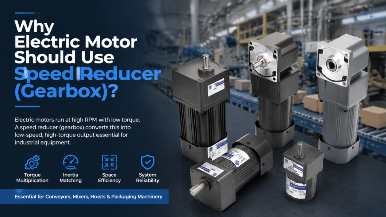
Electric motors are designed to run efficiently at high speeds — typically 1,200 to 3,600 RPM for AC induction motors. Industrial equipment, however, rarely needs that speed. Conveyors run at 30 to 80 RPM. Mixers operate at 20 to 200 RPM. Gate drives and lifts move even slower. The result is a fundamental mismatch: a […]