AC Gear Motor Overheating: 6 Causes and How to Fix Them
A hot gear motor is a symptom. Six causes that explain almost every overheating complaint, the temperature numbers that define too hot, and a ten-minute diagnostic.
Read More
SEW-EURODRIVE is the default specification in a lot of European-designed machinery, and that is exactly why the alternative question comes up: the machine was designed around a gearmotor that now takes twelve weeks to arrive and costs more than the rest of the drive train combined. The question worth asking is not “can anything replace a SEW gear motor” — it is “what specifically can replace the SEW gearmotor on this machine, and what changes if it does.”
This guide is deliberately narrow. It covers compact three-phase AC gearmotors in the 0.2 kW to 3.7 kW band, which is where most small conveying, mixing, packaging and material handling drives sit. It explains which SEW families that band maps onto, the four dimensions that decide whether a replacement bolts up, where a compact integral gearmotor wins, and where it genuinely should not be used. The medium gear reducer motor range is the subject; the boundary is the point.
In the 0.2–3.7 kW band, a compact three-phase AC gearmotor can replace an SEW unit for straightforward constant-speed duty — conveyors, small mixers, agitators, packaging feed rolls, rotary valves, small hoists — provided four interface dimensions match and the destination market does not impose an efficiency class the motor cannot meet.
It cannot substitute for SEW where the application depends on high overhung load capacity, large hollow-shaft mounting, oil-bath industrial gear unit construction, hazardous-area certification, servo-level positioning, or a tender that names SEW explicitly. Those are different products, not different brands of the same product.
SEW’s range is modular and much wider than the compact gearmotor category. Being specific about the overlap is what makes an alternative proposal credible.
| SEW family | Gear type | Where it overlaps the 0.2–3.7 kW band | Substitution position |
|---|---|---|---|
| R series (R17–R97) | Inline helical | Yes — this is the closest match to a parallel-shaft AC gearmotor | Practical, subject to interface dimensions |
| F series | Parallel-shaft helical | Yes at the small end | Practical where shaft height and foot pattern allow |
| K series | Helical-bevel, right-angle | Yes at the small end | Practical where a 90-degree output is needed |
| S series | Helical-worm | Partly — worm boxes have different self-locking behaviour | Proceed with care, see below |
| W series | Spiroplan | Rarely | Different mounting concept |
| X series | Industrial gear units | No | Out of scope |
Two notes that matter. First, the R series covers roughly 0.12 kW to 4.0 kW across R17 to R167, so almost the whole 0.2–3.7 kW band sits inside it. Second, SEW’s smaller helical-bevel units are bevel gearboxes, not worm gearboxes. If someone tells you a compact AC gearmotor “self-locks like the SEW unit did”, check the gear type — bevel and helical units do not self-lock, and neither do ours. Self-locking is a property of worm geometry, not of the SEW brand.
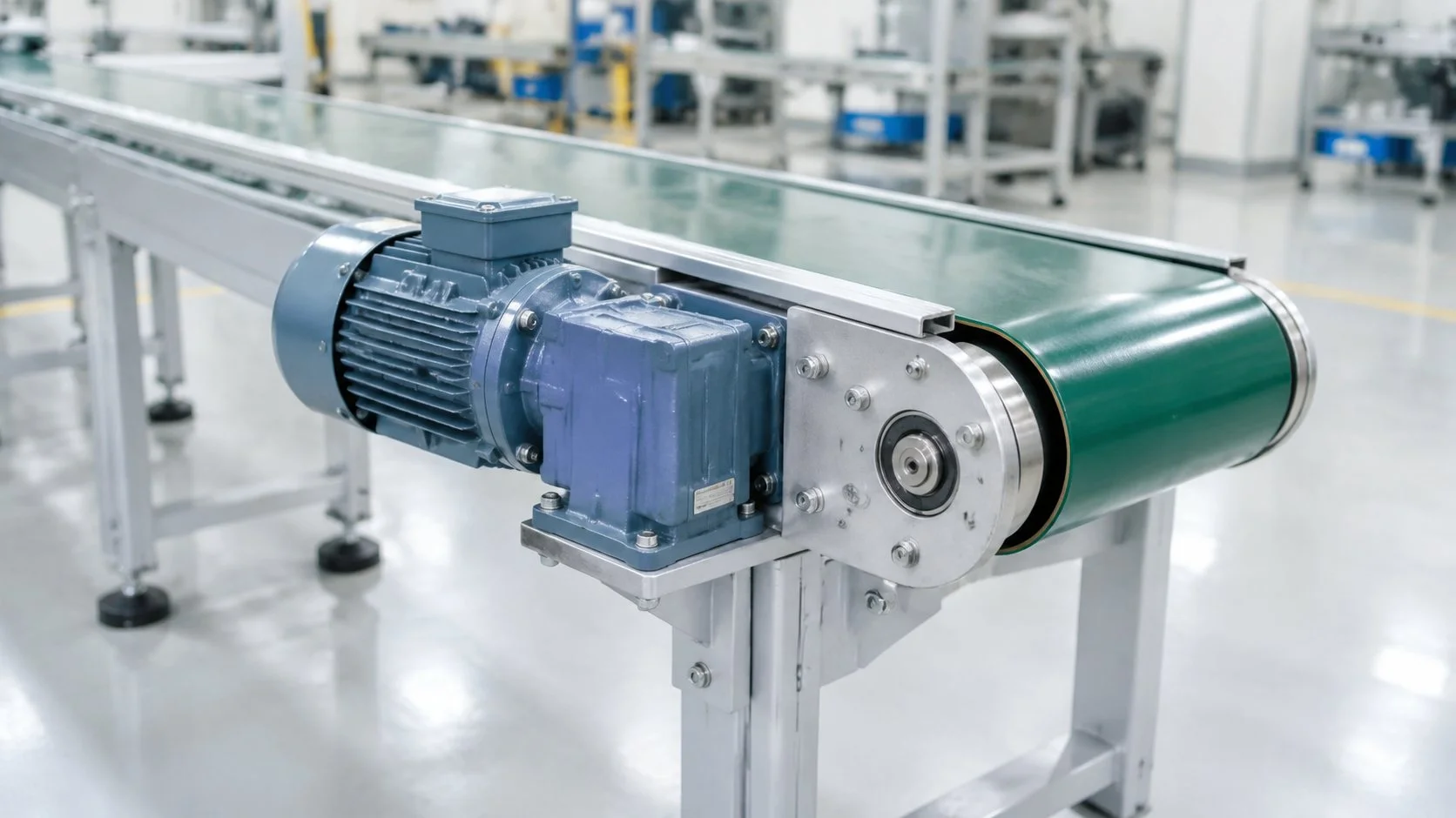
Physical interchange is almost always the binding constraint, not torque. Get these four from the existing drawing before you compare anything else.
| Dimension | Tolerance that matters | Consequence of missing it |
|---|---|---|
| Shaft height (centre height above the mounting feet) | A few millimetres | Coupling misalignment or a new base plate |
| Foot hole pitch and bolt size | Exact | Re-drilling the machine frame |
| Output shaft diameter, length and keyway | Exact, or a new hub | New pulley, sprocket or coupling |
| Flange size and pilot diameter, if flange-mounted | Exact | New mounting plate or adapter |
Claims that a replacement is “dimensionally identical” to 90% of the market should be treated as a starting hypothesis, not a specification. Measure the existing unit. The four numbers above take twenty minutes to capture and eliminate the most expensive class of error in a substitution project.
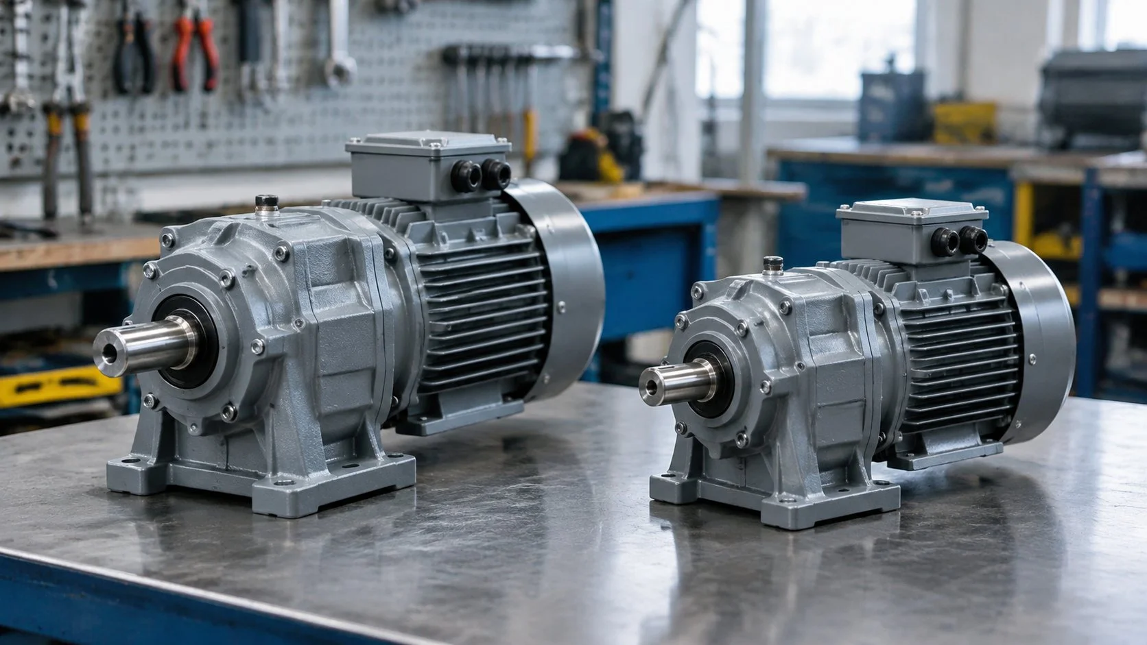
Power alone tells you nothing about whether a gearmotor will move your load. The table below converts the power band into output torque at four output speeds, calculated as T = 9550 × P × η ÷ n with η = 0.90. These are calculated figures, not catalogue ratings — confirm the gearbox rating for the specific ratio before ordering.
| Power | 150 r/min | 100 r/min | 60 r/min | 30 r/min |
|---|---|---|---|---|
| 0.2 kW | 11.5 N·m | 17.2 N·m | 28.7 N·m | 57.3 N·m |
| 0.4 kW | 22.9 N·m | 34.4 N·m | 57.3 N·m | 114.6 N·m |
| 0.75 kW | 43.0 N·m | 64.5 N·m | 107.4 N·m | 214.9 N·m |
| 1.5 kW | 85.9 N·m | 128.9 N·m | 214.9 N·m | 429.8 N·m |
| 2.2 kW | 126.1 N·m | 189.1 N·m | 315.2 N·m | 630.3 N·m |
| 3.7 kW | 212.0 N·m | 318.0 N·m | 530.0 N·m | 1,060.0 N·m |
Two things follow from that table. Torque rises as output speed falls at constant power, which means a 0.4 kW unit at 30 r/min can carry more than twice the torque of a 0.75 kW unit at 100 r/min. And the gearbox, not the motor, is usually what limits the selection: at 3.7 kW and 30 r/min you are asking for over 1,000 N·m, which is a different class of gearbox construction from a compact cast housing. The torque calculation guide covers the conversion in more detail.
An integral gearmotor is a single assembly: one manufacturer, one casting, one warranty. That architecture has real advantages in this power band.
The electrical envelope is part of the cost story too. All of the medium range units are 3-phase only — 0.4 kW, 0.75 kW, 1.5 kW, 2.2 kW and 3.7 kW, all wound for 3-phase 220 V or 3-phase 380 V at 50/60 Hz, with 22 mm to 50 mm output shafts. If your site is single-phase at 0.4 kW and above, this range is not the answer.
The 0.2 kW point is the crossover. At that rating the 200 W compact gearmotor is available in single-phase or three-phase, in an 80–100 mm frame, which is the boundary where the architecture changes from a small-frame gearmotor to a medium 3-phase unit. That single detail decides more retrofit projects than any torque calculation.
A substitution proposal that does not state its own limits is marketing. These are the cases where the answer is to stay with the original specification or to move to a different class of product entirely.
| Condition | Why a compact gearmotor is the wrong answer | What to do instead |
|---|---|---|
| Mandatory efficiency class at 0.75 kW and above | The motor inside a compact gearmotor is a standard-efficiency design, not an IE3 unit | Stay with an IE3/IE4 geared motor, or check whether the market requires it at all |
| High overhung load from a large pulley or long shaft extension | Compact output bearings are sized for modest radial loads | Use a gear unit with a heavy-duty bearing arrangement, or support the load separately |
| Large hollow shaft, shrink disc or keyless mounting | These are industrial gear unit features, not compact gearmotor features | Specify an industrial gear unit |
| Hazardous area with an Ex rating | Standard TEFC construction is not acceptable in a classified zone | Certified Ex-rated drive only |
| Continuous operation in oil-bath, high-thermal-duty service | Grease-lubricated compact housings have a different thermal ceiling | Oil-filled industrial gear unit |
| Positioning, indexing or holding torque | No encoder, no brake as standard, no repeatable position | Servo or a braked geared motor with feedback |
| A tender that names SEW | The specification is the requirement, not the product | Quote the specified product, or get the specification changed first |
This is the point that sinks otherwise sound substitution projects, and it is a regulation question rather than an engineering one.
European ecodesign rules for electric motors set minimum efficiency classes by power band. For three-phase induction motors placed on the EU market, IE3 has applied from 0.75 kW upward since 2021, with IE4 required in the 75–200 kW band from 2023, and the 0.12–0.75 kW band brought into scope on the same timetable. A geared unit is assessed on the motor inside it.
| Market | What touches a 0.75 kW gearmotor | Practical consequence |
|---|---|---|
| EU | Minimum efficiency class applies from 0.75 kW | A standard-efficiency unit is not compliant above 0.75 kW; below that, confirm the current requirement for the power band |
| UK | Equivalent ecodesign regime retained | Same expectation in practice |
| ASEAN (Indonesia, Malaysia, Vietnam, Thailand) | No mandatory motor efficiency class for this band | Efficiency is a running-cost argument, not a compliance gate |
| North America | DOE efficiency rules apply to defined general-purpose motor categories | Check whether the specific motor falls in scope before assuming exemption |
Treat that table as a prompt to verify, not as legal advice — the current text of the applicable regulation governs. The practical takeaway is simple: if your machine is CE-marked and goes to the EU at 0.75 kW and above, the buyer will ask for an efficiency declaration, and a standard-efficiency compact gearmotor will not satisfy it. Below 0.75 kW, and outside the EU, the constraint usually disappears and the cost comparison becomes the deciding factor.
That is also the honest reason this article is scoped to 0.2–3.7 kW rather than “our motors replace SEW”. Below 3.7 kW, a compact integral gearmotor is a reasonable like-for-like in most constant-speed applications. Above it, you are in industrial gear unit territory and the substitution logic changes completely.
| Cost element | Typical position after switching |
|---|---|
| Unit cost of the drive | Lower — this is the visible saving |
| Lead time and working capital | Meaningfully shorter on catalogue frames |
| Spare-parts inventory | Simpler if you standardise on one frame family |
| Engineering time for the retrofit | Higher on the first machine — budget it |
| Efficiency running cost | Potentially higher; quantify it if the machine runs continuously |
| Certification impact | Can be significant if the machine’s CE or safety file names the drive |
The saving is real but it is not the whole cost. The two lines buyers underestimate are engineering time on the first conversion and the certification implication. Both are one-off, which is why the case improves sharply from the second machine onward.
Step 7 is the one that gets skipped. A single instrumented trial unit costs less than one unplanned stoppage, and it converts an assumption into a record you can hand to the next plant.
| Mistake | Consequence | Fix |
|---|---|---|
| Matching power and ratio, ignoring shaft height | Base plate has to be re-made | Measure centre height first |
| Assuming the replacement is dimensionally identical | Delayed retrofit once the machine is stripped | Verify against the drawing, not the claim |
| Overlooking the efficiency class at 0.75 kW+ in the EU | Machine not compliant at the point of sale | Resolve the compliance question before ordering |
| Specifying 0.4 kW+ on a single-phase site | Product does not exist in that configuration | Check the phase requirement at 0.2 kW, where the architecture changes |
| Reusing the original overload relay setting | Nuisance tripping or no protection at all | Set the relay from the new nameplate current |
| Assuming self-locking holding | Load drifts or back-drives when power is removed | Use a brake if holding is a requirement, not the gearbox |
The overload relay point is worth a sentence more. A replacement motor rarely has exactly the same full-load current as the original. Reusing the existing setting gives you either nuisance trips on a hot day or a relay that will not protect the winding. Reset it from the new nameplate. The service factor and thermal sizing guide covers how much margin to leave.
For constant-speed duty in the 0.2–3.7 kW band and where the four interface dimensions match, yes — the R series is the closest architectural match to a parallel-shaft AC gearmotor. Above 3.7 kW, or where the application depends on high overhung load capacity or hollow-shaft mounting, it is not a like-for-like substitution.
The medium range covers 400 W to 3,700 W in five ratings, all three-phase 220 V or 380 V. Below that, the small series covers 15 W to 300 W in single-phase or three-phase, so the 0.2 kW point at the bottom of this article’s scope is served by the 200 W compact unit.
Sometimes, and it has to be measured rather than assumed. Shaft height, foot hole pitch, shaft diameter and length, keyway and flange pilot diameter are the five numbers that decide it. Claims of universal dimensional compatibility should be treated as a hypothesis to verify.
Not at 0.75 kW and above, where EU ecodesign rules require a minimum efficiency class. Below 0.75 kW, and in most ASEAN markets, no mandatory class applies to this band. Confirm the current requirement for your destination market and power rating before you commit.
Yes, the right-angle family covers 25 W to 300 W. For the 400 W–3.7 kW medium range, the units are supplied in vertical and horizontal mounting arrangements. If your machine needs a 90-degree output in the medium band, that is a scoping conversation rather than a catalogue item.
A standard AC gearmotor does not include a holding brake, and neither helical nor bevel gearing self-locks. If the original SEW unit had a brake, that function has to be replaced by a brake, not by the gearbox. The duty rating guide explains what the reversible rating does and does not cover.
If you are evaluating a substitution on a specific machine, send the existing nameplate details and the four interface dimensions with the duty data. We will tell you what matches, what does not, and where the honest answer is to keep the original specification. For the wider SEW range context, the SEW series overview covers the families above this band.